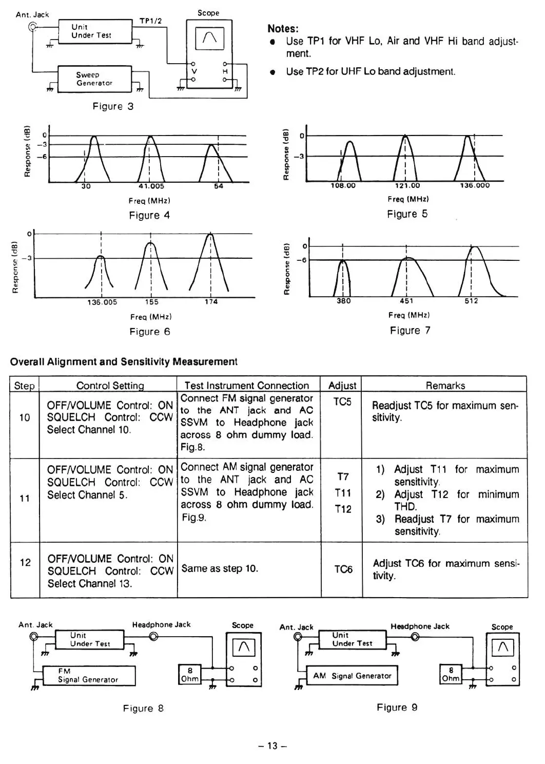
An
t. Jack
Scop
e
TPl
/2
Unit
~
Nates:
Unde
r Test
Use TP1 tor VHF La, Air and VHF Hi band adjust-
.,j,.-
•
ment.
Sweep
•
Use TP2 tor UHF La band adjustment.
Generator
Figure 3
a:
~I
.
ol
"'C
(\
?
1\
(]
».
5\
111
J\
c
0
1\
11
!ti
i-,
~
/
;1
t:
a:
30
41
.00
5
54
108
.00
121
.00
136
.000
Freq
(
MHz)
Freq
(M Hz)
Figure 4
Flgure 5
0
ê:i
ê:i
0
"t;
.
~
::
- 3
~
- 6
c:
'"
c:
0
0
Sr
~
'"
.,
c::
a:
136 .0
05
15
5
174
Freq
(MHz
)
Freq (MHz)
Figure 6
Figure 7
Overall
Alignment
and Sensitivity Measurement
Step Control Settlnq
Test Instrument Connection
Adiust Remarks
OFFNOLUME Control: ON
Connect FM signal generator
TC5
Readjust TC5 tor maximum sen-
to the ANT jack and AC
10 SQUELCH Control: CCW
SSVM to Headphone jack
sitivity.
Select Channel 10.
across 8 ohm dummy laad.
Fig.8.
OFFNOLUME Control. ON
Connect AM signal generator
T7
1) Adjust T11 tor maximum
SQUELCH
Control : CCW
to the
ANT
jack and AC
sensitivity.
11
Select Channel 5.
SSVM
to
Headphone jack
T11
2) Adjust T12 tor
minimum
across 8 ohm dummy laad.
T12
THD.
Fig.9.
3) Readjust T7 tor
maximum
sensitivity.
12
OFFNOLUME Control : ON
Adjust TC6 tor maximum sens
i-
SQUELCH Contral: CCW
Same as step 10.
TC6
tivity.
Select Channel 13.
o
o
Scope
Un
it
Unde
r Test
Signal Generator
,..-...,...,....,.-
__
-,
Heedpho ne Jack
o
o
Scope
Headpho ne Jack
Un
it
Und
er T est
FM
Signal Gener
ator
Figure 8
Figure 9
- 13 -
 Loading...