Step
Control Settlnq
Test Instrument Connection
Remarks
OFFNOLUME
Control :
ON Conneet FM signal generator to the
Turn oft the modulation and mea-
SQUELCH Control : CCW
ANT jack and AC SSVM to Head-
sure the (S
+N)/N ratio.
13
Channel as Table 1.
phone jack across 8 ohm dummy
lead. Set the signal generator to
each trequency as Table
1.
Set the VOLUME control tor 0 dB
(0.775
V)
reading on the SSVM.
Note:
TP6 is used to obserbe the AM band detection output.
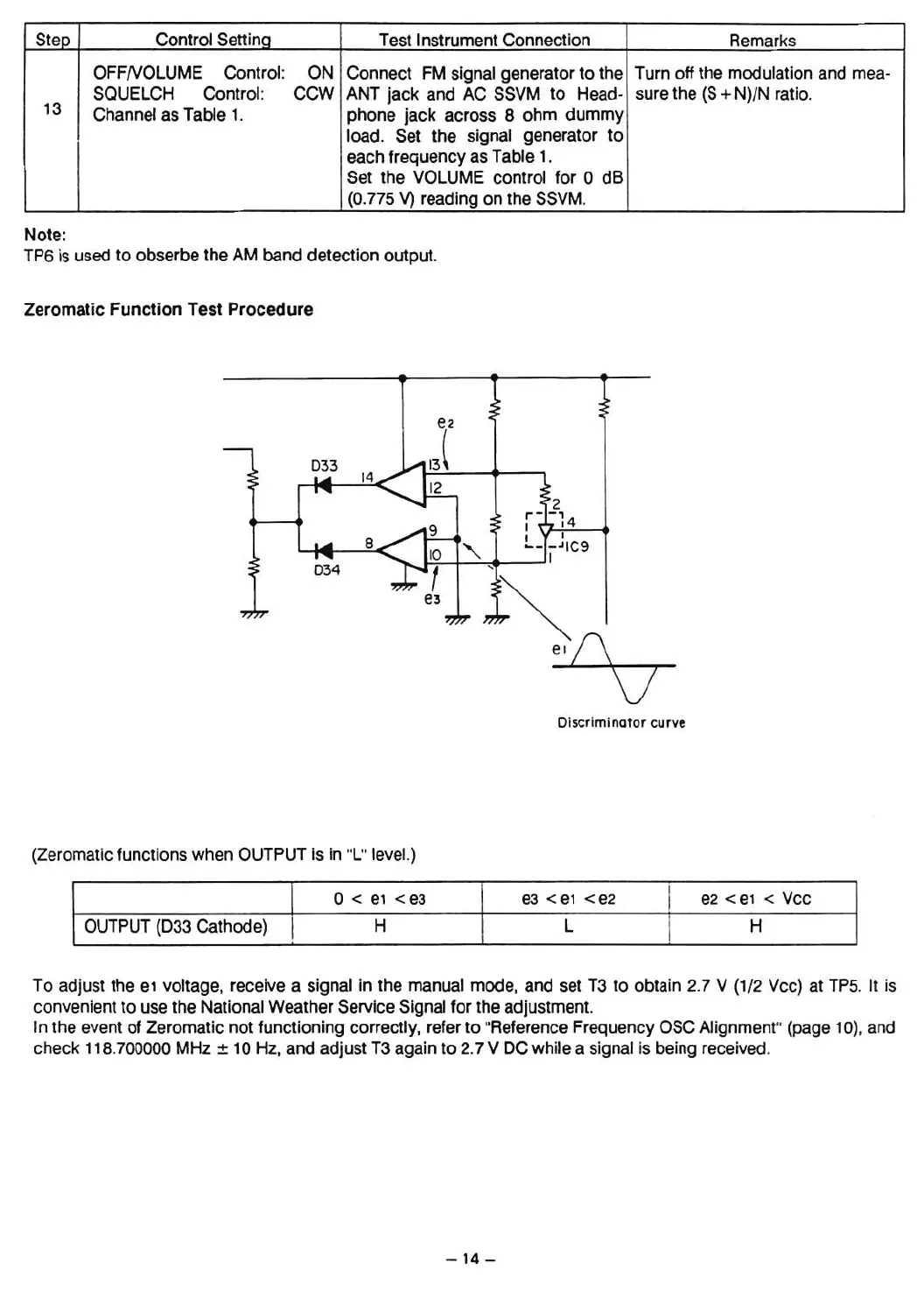
Zeromatic
Function
Test
Procedure
Dlscrirnlnntor curve
(Zeromatic functions when OUTPUT is in "L" leveL)
I
o<
e1
< es
ea <e1 -cea
I
ea <e1 < Vee
I
OUTPUT (033 Cathode)
I
H L
I
H
To adjust the
e1
voltage, receive a signal in the manual mode, and set T3 to obtain 2.7 V (1/2 Vee) at TP5. It is
convenient to use the National Weather Service Signal tor the adjustment.
In the event of Zeromatic not functioning correctly, refer to "Reference Frequency OSC Alignment" (page 10), and
check 118.700000 MHz
±
10Hz,
and adjust T3 again to 2.7 V OCwhile a signal is being received.
- 14 -
 Loading...