MIC Jack
Pin 4
ANT. Jack
50S1 Load
UNIT
UNDER TEST
SPECTRUM
ANALYZE R
or
OSCILLOSCOPE
1
AF GENERATOR
MIC Jack
Pin 4
AF
GENERATOR
POWER
METER
2 Tone SW
ON/OFF
0
/
ANT. Jack
UNIT
UNDER
TEST
5on
Load
MONITOR
SCOPE
AF
GENERATOR
13.8 V
DC POWER
SUPPLY
SPECTRUM
ANALYZER
(if available)
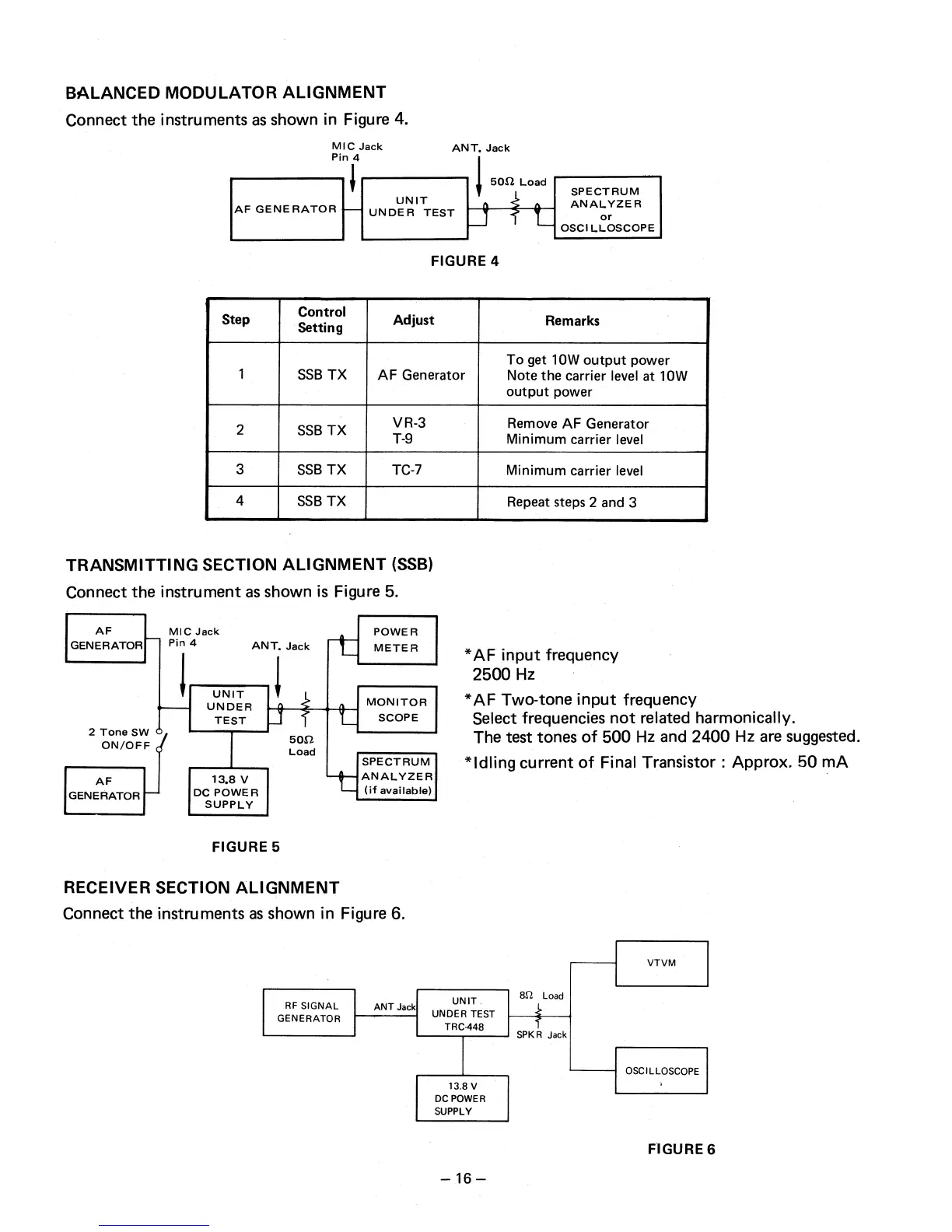
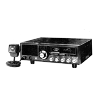
BALANCED MODULATOR ALIGNMENT
Connect the instruments as shown in Figure 4.
FIGURE 4
Step
Control
Setting
Adjust
Remarks
1
SSB TX
AF Generator
To get 10W output power
Note the carrier level at 10W
output power
2
SSB TX
VR-3
T-9
Remove AF Generator
Minimum carrier level
3
SSB TX
TC-7
Minimum carrier level
4
SSB TX
Repeat steps 2 and 3
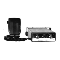
TRANSMITTING SECTION ALIGNMENT (SSB)
Connect the instrument as shown is Figure 5.
FIGURE 5
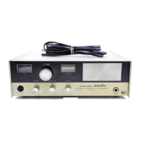
RECEIVER SECTION ALIGNMENT
Connect the instruments as shown in Figure 6.
*AF input frequency
2500 Hz
*AF Two-tone input frequency
Select frequencies not related harmonically.
The test tones of 500 Hz and 2400 Hz are suggested.
*Idling current of Final Transistor : Approx. 50 mA
VTVM
ANT Jack
RF SIGNAL
GENERATOR
UNIT
UNDER TEST
TRC-448
82 Load
SPKR Jack
OSCILLOSCOPE
13.8 V
DC POWER
SUPPLY
FIGURE 6
— 16 —