This document provides assembly instructions for the Realtree UT400-RT UTV, a utility terrain vehicle designed for various tasks and off-road use. The manual emphasizes the importance of reading and understanding the owner's manual for safety, parts, functions, pre-ride inspection, starting, and maintenance before attempting to start the UTV.
Function Description:
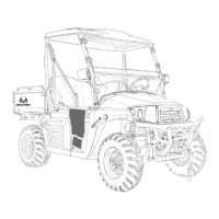
The Realtree UT400-RT is a robust utility terrain vehicle intended for a range of applications, from recreational off-roading to practical utility tasks. Its design suggests a focus on durability and functionality, with features like a roll cage for safety, a front bumper with a winch for recovery or pulling, and a cargo bed for hauling. The vehicle is equipped with a steering wheel for control, a bench seat for occupants, and mirrors for visibility. Safety nets are included to enhance occupant protection during operation. The inclusion of a battery and bracket indicates an electric start system and power for accessories.
Important Technical Specifications (Derived from Hardware and Assembly):
- Hardware Sizing: The manual provides a detailed guide for various bolts, nuts, and washers, indicating the specific sizes used throughout the assembly. This suggests a standardized approach to hardware, simplifying maintenance and part replacement.
- Bolts: M6x60, M6x30, M6x20, M8x15, M8x25-M10x16 Hex Button Bolt, M10x15 Shoulder Bolt, M10x15 Hex Bolt, M10x25 Bolt.
- Nuts: M6 Flange Nut, M8 Flange Nut, M10 Flange Lock Nut, M6 Acorn Nut, M10 Acorn Nut.
- Washers: Curved Washer (Large), M10 Lock Washer, M6 Lock Washer, M8 Shaft Washer.
- Other Fasteners: Rubber Gromet, M8 Cap Post Nut.
- Steering Wheel: Secured with a 12mm lock nut and 6 - 4mm allen bolts. The steering column is designed to accept the steering wheel over groves, ensuring proper alignment.
- Roll Cage: Attached using a combination of M10x15 Hex Head Bolts, M8x25-M10x16 Hex Button Bolts, M10 Lock Washers, M10 Cap Nuts, and Curved Washers (Large). The design ensures the roll cage provides structural integrity and protection.
- Seat Back and Seat Belts: The seat back is secured with M6x16 Bolts, M6 Lock Washers, and M6 Flat Washers. The seat belt assembly uses M10x15 Shoulder Bolts and 14mm lock nuts, indicating a strong and secure attachment for occupant safety.
- Front Bumper & Winch: The bumper braces are attached with M8x45 bolts and M8 lock nuts. The main bumper assembly is secured to the vehicle frame with M10x25 bolts and M10 lock nuts, and to the lower frame with M12x35 bolts. The winch wiring specifies positive (+) and negative (-) connections, indicating a standard 12V electrical system.
- Battery: The battery is secured with an M6X15 BOLT, M6 washer, and M6 Flange Nut for both positive and negative terminals. This suggests a standard automotive-type battery.
Usage Features:
- Steering Wheel Installation: The process involves sliding the wheel onto the steering shaft, securing it with a lock nut, and then attaching a center cap and clamp ring with allen bolts. This ensures a firm and responsive steering mechanism.
- Roll Cage Assembly: The roll cage is designed to be lifted onto mounting locations, with specific instructions for orienting grab bars forward and seat brackets backward. This highlights the importance of correct installation for safety and structural integrity.
- Seat Back and Seat Belts: The seat back is installed with the curved side facing up, and the seat belt bracket is assembled with the curved side facing the center of the vehicle. This ergonomic design ensures comfort and proper restraint. The rear bed latch allows the bed to be in a "dump position," suggesting a tilting cargo bed for easy unloading.
- Front Bumper & Winch: The front bumper includes integrated braces for added strength and a winch for utility. The installation process emphasizes not fully tightening bolts until all hardware is in place, ensuring proper alignment. The winch wiring instructions are clear about positive and negative connections.
- Windscreen: The windscreen is installed using clamps and straps, with Velcro backing for secure attachment. This provides protection from elements during operation.
- Mirrors: Driver and passenger side mirrors are installed using 4mm Allen screws, enhancing visibility and safety.
- Battery Installation: The battery is placed in a dedicated box under the driver's seat, with specific instructions for connecting positive (RED) wires before negative (BLACK) wires to prevent electrical hazards. A battery bracket secures the battery in place.
- Safety Net: Safety nets are installed using latch straps and a floor bracket, ensuring they are securely in place to protect occupants.
Maintenance Features (Implied by Assembly and Hardware):
- Standardized Hardware: The extensive list of metric hardware (M6, M8, M10, M12) suggests that replacement parts for fasteners should be readily available, simplifying repairs and maintenance.
- Accessible Components: The assembly instructions detail how various components are attached, implying that they can be disassembled for maintenance or replacement. For example, the battery is located under the driver's seat for easy access.
- Pre-Ride Inspection: The manual's emphasis on "pre-ride inspection" in the owner's manual indicates that regular checks of components like steering, brakes, and safety features are crucial for safe operation.
- Clear Wiring Instructions: The specific instructions for connecting winch and battery wires facilitate correct electrical maintenance and troubleshooting.
- Tool Requirements: The manual lists specific tools (socket wrenches, Allen head wrenches, Phillips head screw drivers) required for assembly, which would also be necessary for maintenance and repairs. This helps users prepare for any necessary work.