Owners/Installation Manual – Controller v2 | Reclaim Energy
RECLAIMENERGY.COM.AU
31
5/6
Purchase Modbus Cable from Reclaim Energy.
Replace the Modbus Cable by following the instructions
below:
1. Switch off the mains power and disconnect the Reclaim
Controller and Heat Pump.
2. Disconnect the ring terminals of the existing Modbus
cable from the Modbus Port of the Heat Pump.
3. Use a Pozidriv screwdriver to undo the four controller
casing screws from the back and remove the front casing.
4. Use a Flathead screwdriver to unscrew the existing
Modbus cable from terminal block J5.
5. Remove cable tie from the rubber grommet.
6. Remove the existing Modbus cable from the controller
by pulling gently.
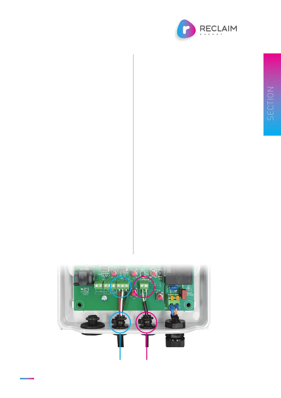
7. Push the un-insulated ferrules of the new Modbus cable
through the rubber grommet, place them in terminal
block J5 (RED wire to “A”, WHITE wire to “B”, and BLACK
wire to “GND”), and tighten the screws.
8. Place a cable tie around the rubber grommet.
9. Put the front casing back on and tighten the casing
screws.
10. Connect the ring terminals of the new Modbus cable to the
Modbus Port of the Heat Pump following the colour code
(RED to RED, WHITE to WHITE, and BLACK to BLACK).
11. Reconnect the Reclaim Controller and Heat Pump, and
switch on the mains power.
Purchase Temperature Sensor Cable from Reclaim Energy.
Replace the Temperature Sensor Cable by following
the instructions below:
1. Switch off the mains power and disconnect the Reclaim
Controller.
2. Use a Pozidriv screwdriver to undo the four controller
casing screws from the back and remove the front
casing.
3. Use a Flathead screwdriver to unscrew the existing
sensor from terminal block J4.
4. Remove cable tie from the rubber grommet.
5. Remove the standard sensor from the controller by
pulling gently.
6. Push the un-insulated ferrules of the new sensor
through the rubber grommet, place them in terminal
block J4 (no polarity), and tighten the screws.
7. Place a cable tie around the rubber grommet.
8. Put the front casing back on and tighten the casing
screws.
9. Reconnect the controller and switch on the power.
10. Check that the sensor is reading correctly.
Figure 5. Modbus Connection Figure 6. Temperature Connection
6 HOW TO EXTEND THE
MODBUS CABLE
5 HOW TO EXTEND THE
TEMPERATURE CABLE
 Loading...