32
12. Adjustments & Maintenance
Fig 12.13
Fig 12.16
The cutter block in this machine is designed to hold three blades.
Never attempt to use the machine if any of the blades are
missing or damaged. Replacement blades must conform to
BS EN 847-1.
Changing the Planer Blades
CAUTION! This procedure involves close contact with the planer
blades. Ensure that protective gloves are worn at all times to
prevent injury to hands.
To make setting the blades an easier and faster operation,
Record Power offer the RPPSJ Planer Blade Setting Jig. Please
see online for full details.
Check the height of the Blade
The blades should be periodically checked for sharpness and position.
Adjustments should be as precise as possible to a tolerance within 1- 1.1
mm to prolong the sharpness of the blades.
Improperly adjusted blades can unbalance the cutterblock and shorten
bearing life as well as producing substandard results.
The planer blades fitted to this machines are made from high speed
steel and can be sharpened to maintain their cutting edge and optimise
performance of the machine. The process of sharpening blades will remove
a small amount of material from the blade's edge and will therefore reduce
the overall width of the blade. Never attempt to use blades that have been
reduced by more than 25% of their original width. Always ensure that the
blade can be held securely by the blade holder. Replace defective blades
immediately.
Caution: Before carrying out any adjustments or maintenance
ensure that the machine is isolated and disconnected from the
electricity supply.
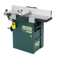
Checking the Height of the Blades
Remove the bridge guard to give access to the top of the cutter block.
Raise both tables into the upright position to give access to the sides of the
cutter block, Fig. 12.13.
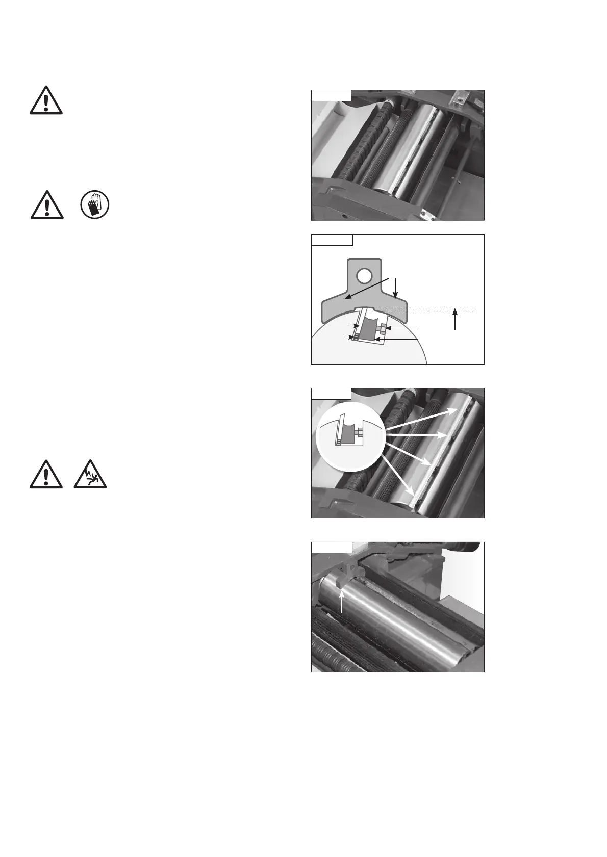
Position the blade setting jig over the blade as shown in Fig. 12.14. The
outer pads of the jig should sit fully on the cutter block. If the blade is set
correctly it should be just touching the recessed area of the jig. If the blade
does not touch the middle slot, or if it causes the outer pads of the gauge
to not sit flush then it must be adjusted. The blades should protrude from
the cutter block by a maximum of 1.1 mm.
Adjusting the Height of the Blades
Each blade is held in the cutter block by a blade holder which runs the full
length of the cutter block. The blade holder is secured in place by 4 blade
holder screws which are spread across the length of the holder as shown
in Fig. 12.15. Beneath the blade is a spring which pushes it upwards when
the screws are loosened.
Carefully turn the cutter block until the first blade is at top dead centre.
Loosen each blade holder screw enough to allow the blade to move.
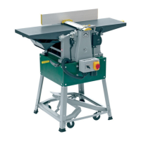
Place the blade setting jig as shown in Fig. 12.16 over the blade at one
end of the cutter block. The spring will push the blade up to meet the recess
in the blade setting jig. Tighten the blade holder with the screw just enough
to keep it in place but allow movement at the other end.
Repeat this process at the opposite end of the cutter block then fully tighten
all blade holder screws.
Repeat the above process on the remaining 2 blades.
Fig 12.14
Blade setting jig
Blade
setting jig
Outer pads
1.1 mm
max
Cutter block
Fig 12.15
Blade
Holder
Screw
Spring
PT107 Manual 3.2.indd 32PT107 Manual 3.2.indd 32 25/04/2022 14:44:0725/04/2022 14:44:07