21
8. Operation
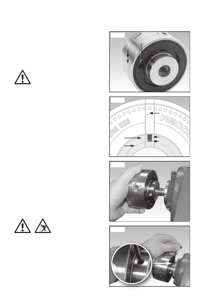
Fig 8.7
On the side of the chuck body is a hole for the blind set
screw, Fig 8.5. The rear of the SC4 also features a slot
which allows access to the hole from the rear, to help
with positioning the blind set screw, Fig 8.5.
Insert the protective leather disc into the hole, ensuring
it is positioned to be touching the insert thread as shown
in Fig 8.6.
Warning: It is essential that the protective
leather disc is used in order to stop the insert
thread being damaged by the blind set screw.
Insert the blind set screw so it is positioned as shown in
Fig 8.6 (SC4 shown), with the hex socket facing towards
the outside of the chuck.
Tighten the blind set screw to hold the chuck insert in
place using the 3 mm hex wrench.
The chuck can now be mounted to the lathe as shown
in Fig 8.7 by threading it carefully onto the spindle until
the insert meets the face of the shoulder on the
spindle nose.
Inserts with certain thread sizes feature a tapped hole
on their collar and are supplied with a protective leather
disc and M6 x 6 mm blind set screw. This allows the
insert to be secured to the lathe spindle, meaning the
chuck can be used on a lathe capable of reverse turning.
See the chapter Contents of the Packages for a list
of these inserts.
If the lathe is to be used in reverse, the chuck must be
secured to the spindle to prevent it from coming loose
during operation. When the chuck is fully threaded onto
the lathe spindle, place the protective leather pad in the
hole on the side of the insert, thread in the M6 x 6 blind
set screw and tighten, Fig 8.8.
Warning: Only use the specified inserts for
reverse turning. Inserts which do not feature a
tapped hole for a securing screw cannot be used
safely if the lathe direction is reversed.
Fig 8.6
Channel
Blind set screw
Rear view of SC4
Protective
leather disc
Insert
Insert
thread
Fig 8.8
Fig 8.5
Blind set
screw hole
Corresponding
slot
SC3 & SC4 Manual 3.7.indd 21SC3 & SC4 Manual 3.7.indd 21 22/04/2022 13:05:4722/04/2022 13:05:47