3.0 How to Enter Programming Mode
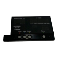
The Config Switch refers to two copper-plated holes located on the circuit-board,
which are accessible through the two small, parallel holes in the hexagonal indent (see
Figure 4 below).
Figure 3: Config Switch. Note the two copper plated holes on the underlying circuit board.
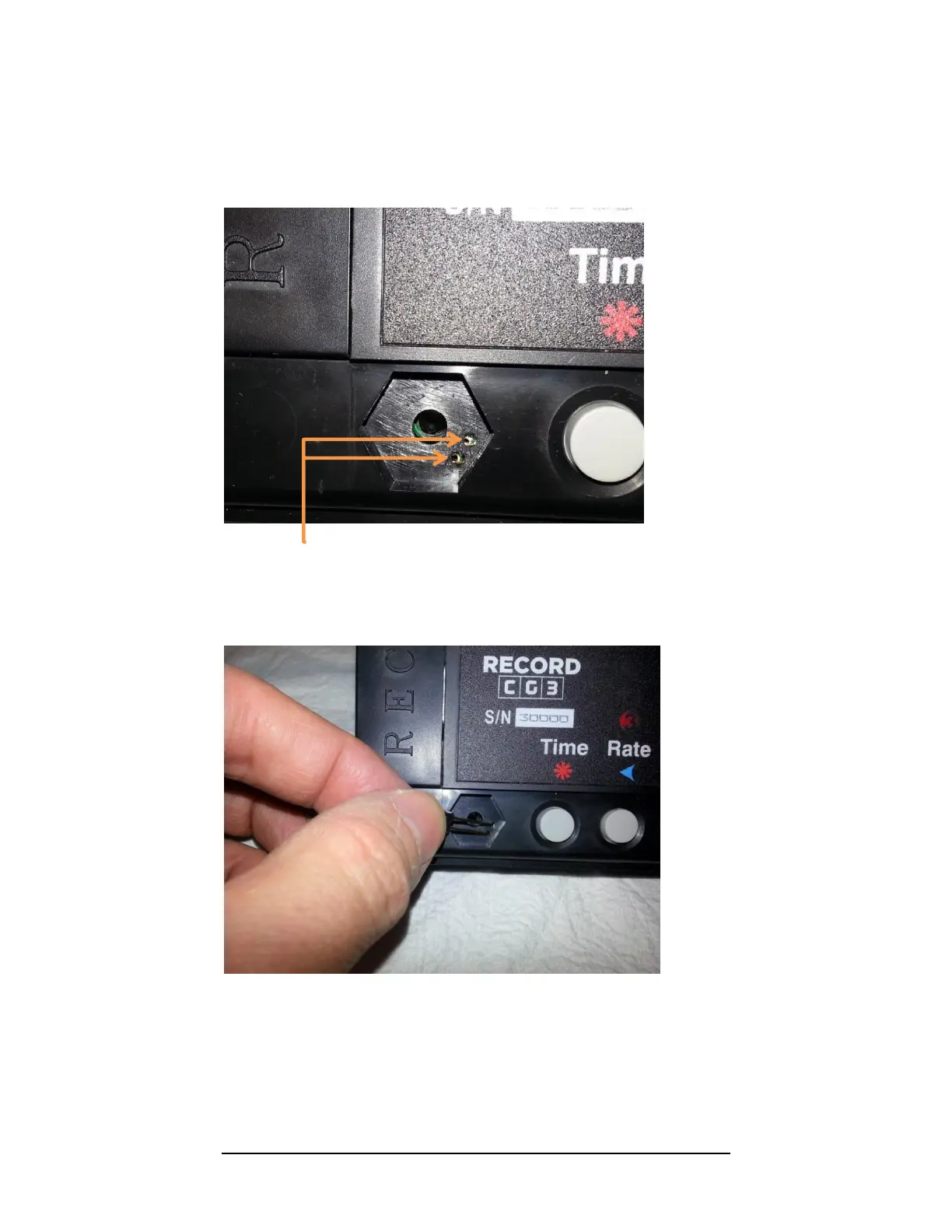
To activate the Config Switch, you have to short the two plated holes together. This can
be done, either with a programming pin (these are usually provided with CG3 upon
purchase), or simply with a piece of wire (we find that a paper-clip works the best).
Figure 4: Activating the Config Switch, using the rate-set pin. Contact must be made with the two copper-plated
holes on the circuit-board inside the taximeter case, in order to short the holes together..
The CG3 will display “SEC 0”, the Security Code Prompt when you have successfully
done so (see next page). You can remove the programming pin and proceed to the next
page.