Operating instructions DFA 127 Full Power Rev. B 11/2006 Page 5 of 20
4 Construction and Function
4.1 Construction
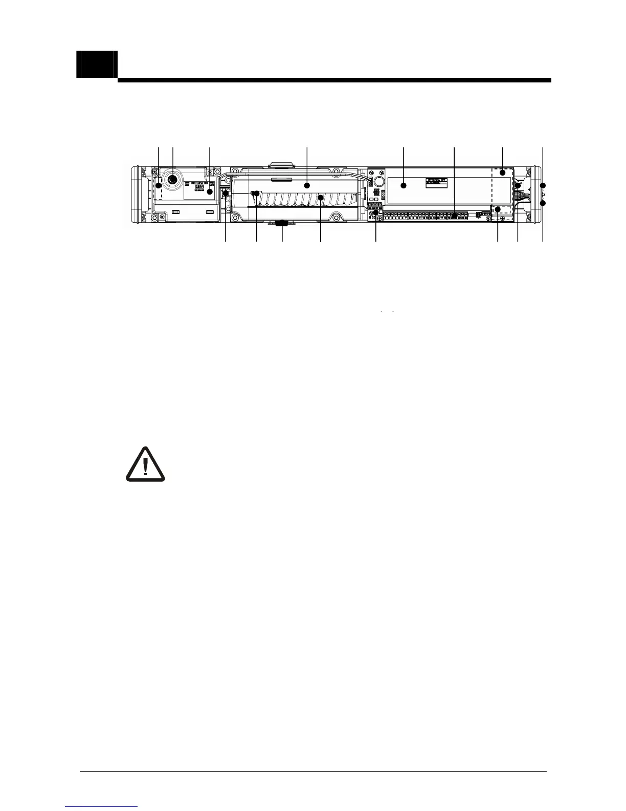
Key to illustration:
1 Mains connection terminals 9* Slide switch S1 (rotating direction)
Multifunctional switch MF on STG
3 Power supply NET 11 Closing spring
4 Drive unit ATM 12 Vision panel adjust. spring tension
5 Control unit STG 13*
Adjusting screw for spring tension
6 Connection terminals control unit 14 Connectors for arms (both sides)
7 Motor print MOT 15 Standard switch BDI
8 ATE drive unit terminals 16 Status signal and Reset button
* Do not change any settings or adjustments! These operations are re-
served exclusively for trained and authorized persons.
4.2 Components
The record DFA 127 swing door operator forms part of an electromechanical swing
door system and comprises the following main components:
Control unit STG: Intelligent, learning, microprocessor-controlled control
system.
Driving unit ATE: Low maintenance DC geared motor with electronic path
measurement and integral thermostatic protective
switch, gear box with adjustable spring tension.
Power supply NET: Compact 230 V power supply with integral input filter
and over-voltage protection.
Control unit BDE: As required with convenient, simple mechanical control
unit and / or a programmable electronic BDE-D.