Do you have a question about the Record DFA127 and is the answer not in the manual?
Provides the name and address of the product manufacturer.
Specifies the document name, article number, and version for reference.
Contains essential copyright, target audience, and storage information for the manual.
Details the DFA 127 as a compact, microprocessor-controlled swing door operator.
Explains the two types of arms (standard/slide) and their use for power transmission.
Covers external control units, master/slave configurations, and cladding options.
Explains the meaning of various symbols (NOTICE, IMPORTANT, CAUTION, WARNING, DANGER) used in the guide.
Lists general regulations for safe operation, including warnings about door movement.
Covers state of technology, intended use, and risks of misuse.
Addresses security, surveillance, and warnings on the product itself.
Outlines requirements for automatic swing doorsets, including safety devices.
Details detection requirements for persons during door cycles according to EN 16005.
Specifies minimum protected widths and radii based on doorset travel time.
Addresses preventing finger trap hazards at the secondary closing edge.
Illustrates required safety distances in millimeters for different configurations.
Emphasizes proper positioning of activation devices for radar motion sensors.
Details manual opening forces and kinetic energy limits for low-energy drives.
Covers opening/closing times and other requirements per EN 16005.
Discusses sensor activation zones and requirements for escape routes.
Covers marking of operating modes and protection of access codes.
Specifies clear recognition of transparent door leaves using marking or labels.
Details requirements for protective measures like enclosures to prevent access to danger points.
Emphasizes operator instruction, user handbooks, and regular maintenance checks.
Presents a graph and formula relating door leaf weight and width to mass inertia.
Details manual opening forces and kinetic energy limits for low-energy operators.
Provides tables for minimum opening/closing times based on door width and weight.
Identifies various components of the DFA 127 operator with a key and diagram.
Explains how the DFA 127 operates without power and its safety functions like collision detection.
Illustrates the standard arm for door leaf connection.
Illustrates the slide arm for pulling door leaves.
Illustrates the slide arm for pushing door leaves.
Shows how lever adapters connect the operator to standard arms.
Illustrates lever adapter connections for slide arms and provides a table of dimensions.
Describes the optional skirt ring for reinforcing lever adapter connections under stress.
Provides instructions and cautions for removing and handling lever adapters.
Shows installation dimensions for standard arms and article numbers.
Provides important notes and cautions regarding the mounting of the operator on the door leaf.
Illustrates installation dimensions for slide arm pulling configurations.
Illustrates installation dimensions for slide arm pushing configurations.
Shows the dimensions for the 85 mm operator chassis.
Shows the dimensions for the 108 mm operator chassis, noting requirements for SFR 127.
Displays the dimensions for 85 mm and 108 mm operator casings.
Provides a detailed diagram for installing standard arms.
Offers a second detailed diagram for installing standard arms.
Shows installation dimensions for slide arms (pulling and pushing).
Provides a second diagram for slide arm installation (pulling and pushing).
Lists checks for door leaf movement, lock engagement, and base stability.
Guides on marking drilling positions, fixing templates, and drilling boreholes.
Warns about spring tension release and provides steps for mounting the operator.
Explains how to adjust spring tension based on door width and EN standards.
Lists checks for arm angle, door leaf movement, and operator damping.
Details the STG 127 control unit's operation and safety compliance.
Covers power supply fusion and connection, referencing wiring diagrams.
Instructs on connecting sensors and door openers with power off.
Guides on positioning jumpers and checking external jumpers for auxiliary units.
Explains sensor installation and monitoring for safe door operation.
Provides wiring schemes for safety sensors (SIO, SIS) and compliance notes.
Explains how to adjust the angle using serrations and provides tightening torques.
Details how to adjust linkage rod length and provides tightening torque.
Outlines technician requirements and general commissioning principles.
Specifies the necessary knowledge for technicians regarding functions and controls.
Lists manual checks for door movement, sounds, screw tightness, and casing position.
Details checks for terminal blocks, cable fastening, and motor connections.
Covers compliance with EN 16005 and checks for automatic reverse and emergency functions.
Introduces the CAN bus, its topology, and termination requirements.
Explains general bus structure and installation with motion sensors.
Emphasizes using specified cables for trouble-free CAN bus operation.
Details the CAN connector, required drill hole size, and connection elements.
Guides on positioning DIP switches for addressing sensors before bus connection.
Explains how to correct wrong sensor addresses and the procedure for modification.
Details how to deactivate faulty sensors and the procedure for replacement and learning.
Describes the simplified start-up procedure using the BDE-D, including language selection and menu navigation.
Refers to a table for checking STG LEDs according to their function.
Details checks for BDE positions (permanently open, locked, one-way).
Refers to the Operating Instructions chapter for details on setting door speeds.
Directs to the Configurations chapter for details on customer-specific settings.
Outlines steps for checking safety functions like automatic reverse and safety devices.
Explains how to test automatic reverse function by obstructing the door.
Refers to Configurations chapter for touch control setup and describes its function.
General check of all DFA functions and tightening the arm screw.
Covers instructing the client, handing over the manual, and demonstrating resets.
Explains the STG 127 control unit, including jumpers, LEDs, and the multifunctional key (MF).
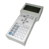
Introduces the BDE-D controller, its operation, and LCD display.
Guides on addressing the electronic controller for single or dual BDE-D installations.
Details door behavior in Automatic, Manual, One-Way, and Continuously Open modes.
Explains the 3-position mechanical BDI toggle switch for setting operating modes.
Describes the function of the reset button for the control unit.
Explains the status display LED indications for faults and resets.
Provides a table of parameters, their factory defaults, and comments for basic operator setup.
Lists and explains parameters related to driving cycle, opening/closing speeds, and acceleration.
Provides notes on BDE-M/4-positions connection and terminal connections.
Shows function charts for mechanical BDE and toggle switch settings.
Illustrates wiring for a time switch to enable the "locked" mode.
Explains the use of Master/Slave control for double-leaf doors and safety functions.
Describes obstacle recognition, reversing, and master/slave installation operation.
Details commissioning differences, connections, safety devices, and parameter settings for Master/Slave.
Explains enabling interlock mode with one BDE-D/BDI for two doors via CAN-isolator.
Guides on setting operators to master/slave via Jumper J14 and connecting via CAN-isolator.
Describes BDE-D functions and states for interlock mode (interlock, no interlock, automatic).
Explains interlock operation with FEM 1, emphasizing one door opening at a time.
Shows configuration settings for FEM-Type and Door System interlock modes.
Illustrates basic wiring diagrams for interlock control using FEM 1.
Explains how to deactivate interlock mode using the "Interlock-Off" switch for simultaneous opening.
Shows wiring diagrams for interlock sequence control with and without sensors.
Mentions pushbutton installation inside the interlock.
Illustrates wiring for optical or acoustic signals indicating interlock occupancy.
Describes replacing the gearbox cover with one that includes a position switch.
Details the FEM 1 module's nameplate, connections, inputs, and outputs.
Explains how to interpret general and BDE-D specific status and error messages.
Explains how fire door operators are differentiated and marked.
Confirms that all convenient arm types can be used with DFA 127 for fire doors.
Details how to adjust closing time for fire doors using jumper settings on the MOT board.
Covers parameter settings for fire alarm system activation on fire doors.
Provides authorization data for fire door and low-energy operator combinations.
Shows a certification mark related to safety standards.
Mentions the use of Master/Slave for appropriate closing sequence in bi-parting doors.
Illustrates the cable layout diagram for the DFA 127 system.
Provides the detailed wiring diagram for master and slave DFA 127 configurations.
| Brand | Record |
|---|---|
| Model | DFA127 |
| Category | Door Opening System |
| Language | English |