Installation DFA 127
11
102-127108955 V1.1 34/ 102
Installation DFA 127
Checking the installation site
▪ Does the door leaf move easily over its entire swing range?
▪ Does the door leaf fall cleanly into the lock?
▪ Have all damping devices been removed (not simply reset)?
▪ Is the base on which the DFA 127 is to be mounted sufficiently stable? The chassis must
lie as flat as possible. Coarse unevenness must be cleared or the bearing area must be
made more powerful or be strengthened by means of additional plates.
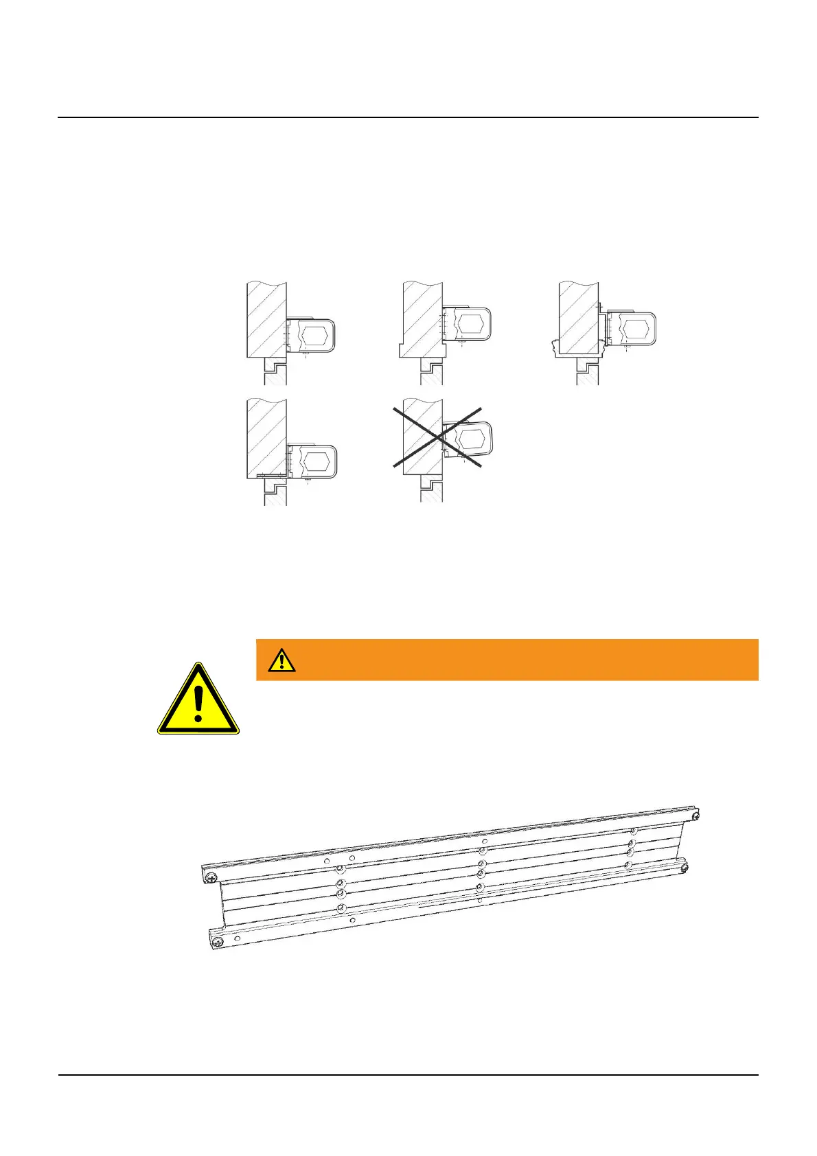
Positioning the DFA and arm
▪ Mark the drilling positions on the template according to the type of installation, the
mounting plate and the arm.
▪ Fix the template to the corresponding position.
▪ Drill the boreholes. After the first borehole the chassis can be used as template.
Mechanical installation of the DFA
WARNING
Spring tensions could suddenly release if casing is opened or disassembled.
• Injuries through flying parts.
Do not open or disassemble the casing.
▪ Dismount the power supply and gear drive unit of the operator.
▪ Fix the mounting plate, place the cables in position and mount any flexible connections.
▪ Install the ATM operator module.
11
11.1
11.2
11.3