Configurations
16
102-127108955 V1.1 81/ 102
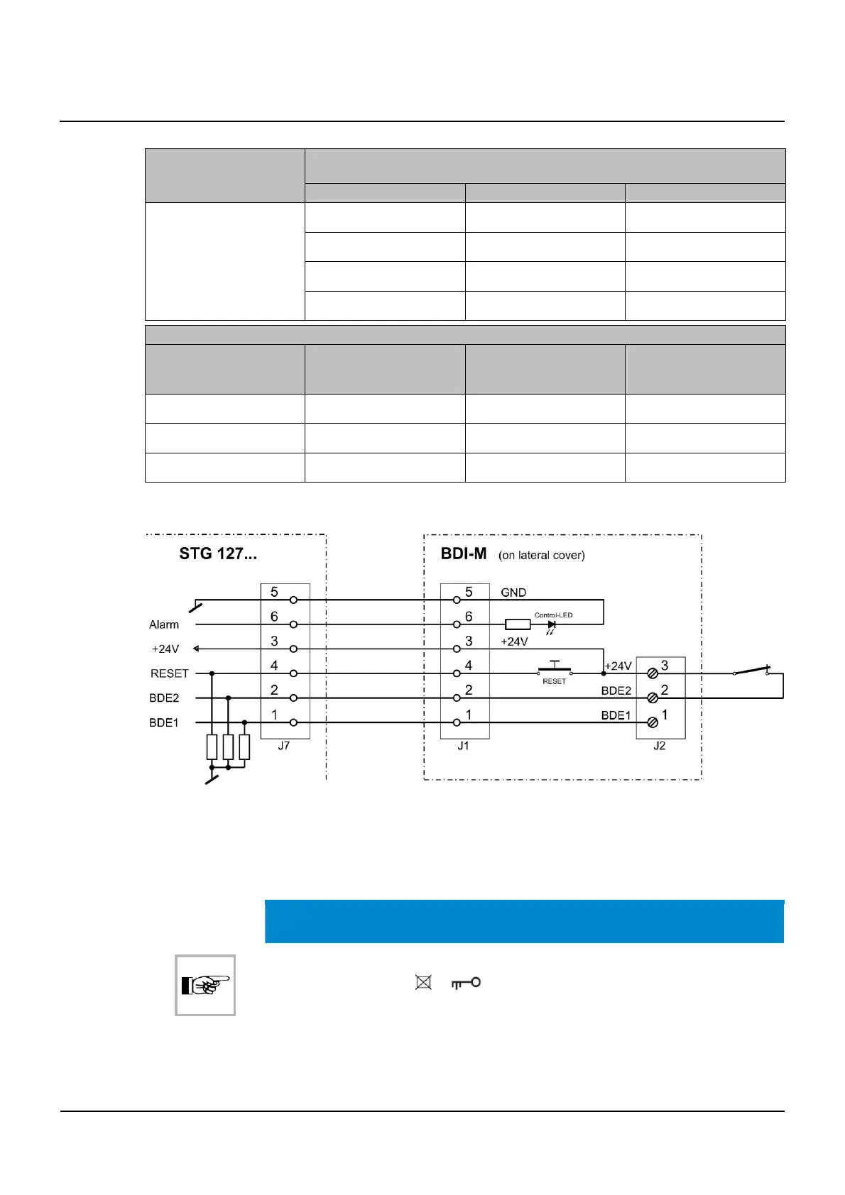
Function chart:
Mechanical BDE (external BDE)
MS BDE-M (102-016841000)
BDE2 / clamp 2 BDE1 / clamp 1 Function
L L locked
L H continuously open
H H manual
H L automatic
Toggle switch BDI on the side cover or external
BDE2 / clamp 2 BDE1 / clamp 1 Function if the external
mech. BDE is not con-
figured
Function if the external
mech. BDE will be con-
figured
L H continuously open continuously open
H L manual automatic
L L automatic locked
(L = interruption or 0 V, H = +24 V)
Connection of a time switch for "locked" (SUR-V)
* Contact closed = mode of operation according to the position of
the operation switch
Contact open = Mode of operation
Locked
NOTICE
In combination with a BDE-D control unit, it is recommended to activate the con-
trol lock of the BDE-D (
or ).
Otherwise, the door can no longer be unlocked using an external mechanical
BDE-M or external signals to the BDI-M circuit board after selection of the
Lo-
cked
operating mode if it has been locked in the meantime with the BDE-D!
16.3.1
16.4