Commissioning DFA 127
13
102-127108955 V1.1 45/ 102
The CAN-Bus
The bus topology
IMPORTANT
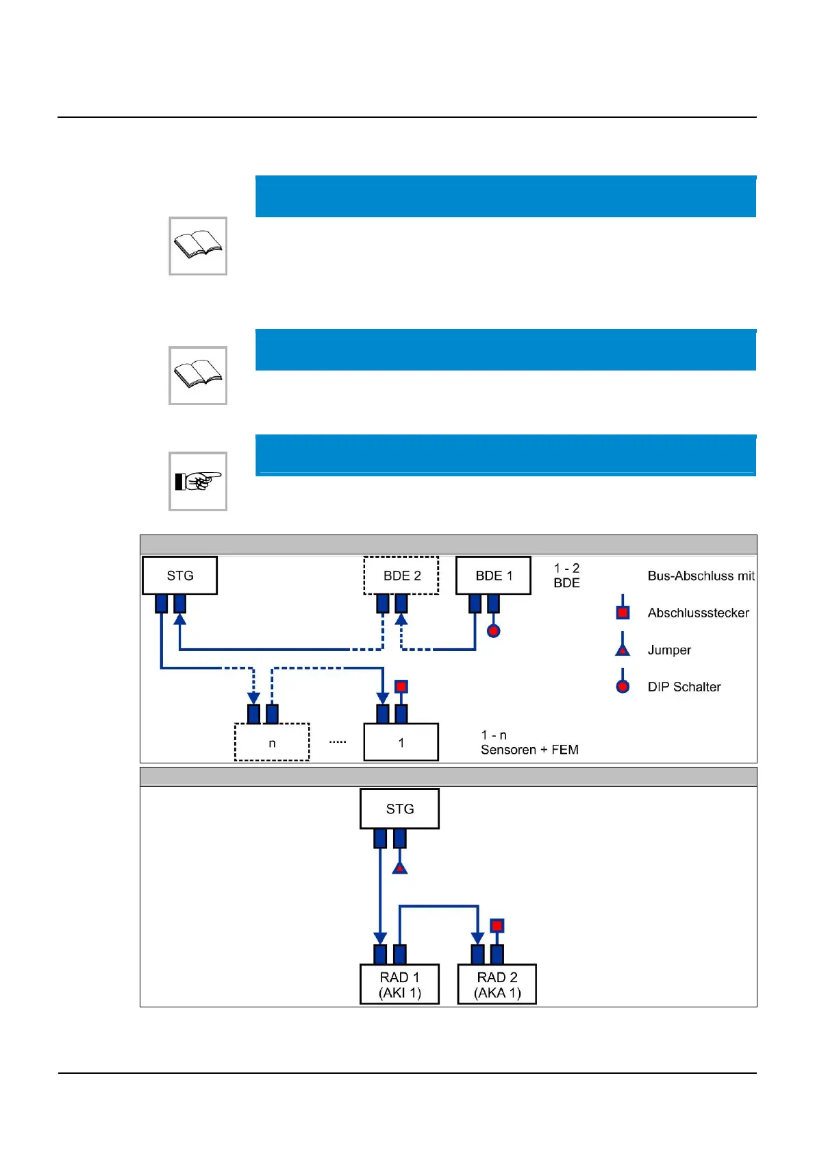
Every bus component has two plug connections, which must both be plugged for
correct wiring.
The bus must basically be terminated at both ends with a terminating resistance
(120 Ω).
IMPORTANT
Make sure that no CAN sockets are left unplugged. Either all sockets are used or
they will be plugged witha terminating resistor.
NOTICE
The BDE-D is always delivered with a terminating resistor connected to it.
The second terminating resistor is located in STM (Jumper J8)
General Bus structure
Installation with 2 motion sensors
13.2
13.2.1