Operating instructions DFA 127 Full Power Rev. B 11/2006 Page 9 of 20
Operating instructions
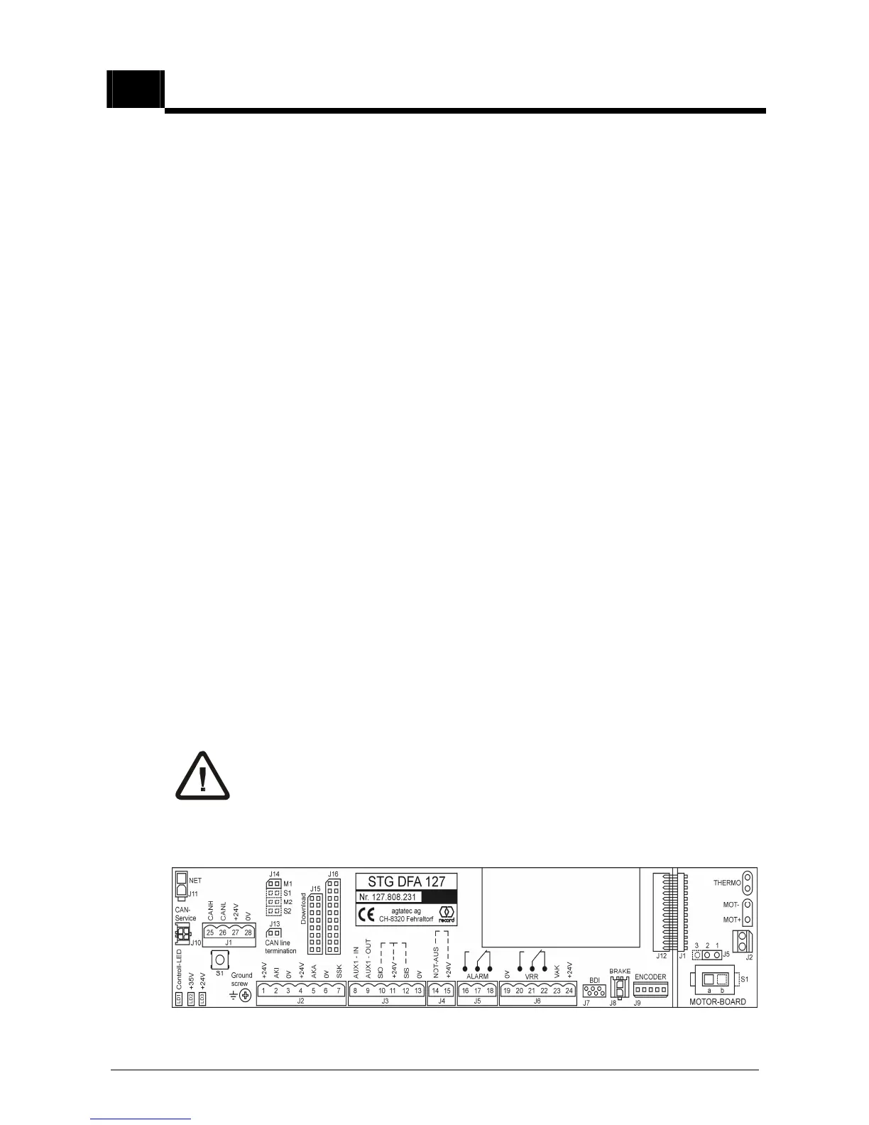
5.2 Auxiliary controls on the control unit STG 127
General:
The CONTROL UNIT STG 127 operates with active HIGH level, i.e. a +24 V level
must be applied to activate a function. Safety inputs are activated during interrup-
tions.
The signal ground (0V) is connected to protective earth.
Jumpers:
J14: Master / Slave
jumper at position M1 for master (factory setting)
jumper at position S1 for slave
J13: CAN line termination
LED’s:
LD1: (red) control LED for push-button operation (S1)
LD2: (green) +35V
Off for power failure
LD3: (green) +24V
Lights if +24V present.
Caution: in the event of a power failure processor reset takes
place 1 second after this LED extinguishes.
Push button S1
This is a multifunctional switch on controller (MF).
The use of this switch is reserved exclusively for trained and authorized
persons.
Top view of the control unit STG: