COPYRIGHT © 2013 RED.COM, INC
RED DSMC OPERATION GUIDE
955-0020_V5.1, REV-D | 80
BRAIN GPIO
Camera Input: Select one of the following options to configure the input for devices connected to the SYNC
connector on the brain:
‒ Sync In: The camera input is used as a sync-in signal for MoCo.
‒ General Purpose In: Use the Brain GPI In High/Low drop-down menus to map inputs to actions.
Camera Output: Select one of the following options to configure the output for devices connected to the
CTRL connector on the brain:
‒ Sync Out: Provides an output sync signal to act as a shutter start tally.
‒ Recording Indicator Out: Provides a signal when recording is in process.
NOTE: For more information about connectors, go to “Input/Output Connectors” on page 129.
GEN AND SYNC STATUS ICONS
The Lower Status Row of the camera display has GEN and SYNC icons, which change color based on the
current genlock and sync statuses. For information about what each color indicates, go to “Icon Behavior” on
page 45.
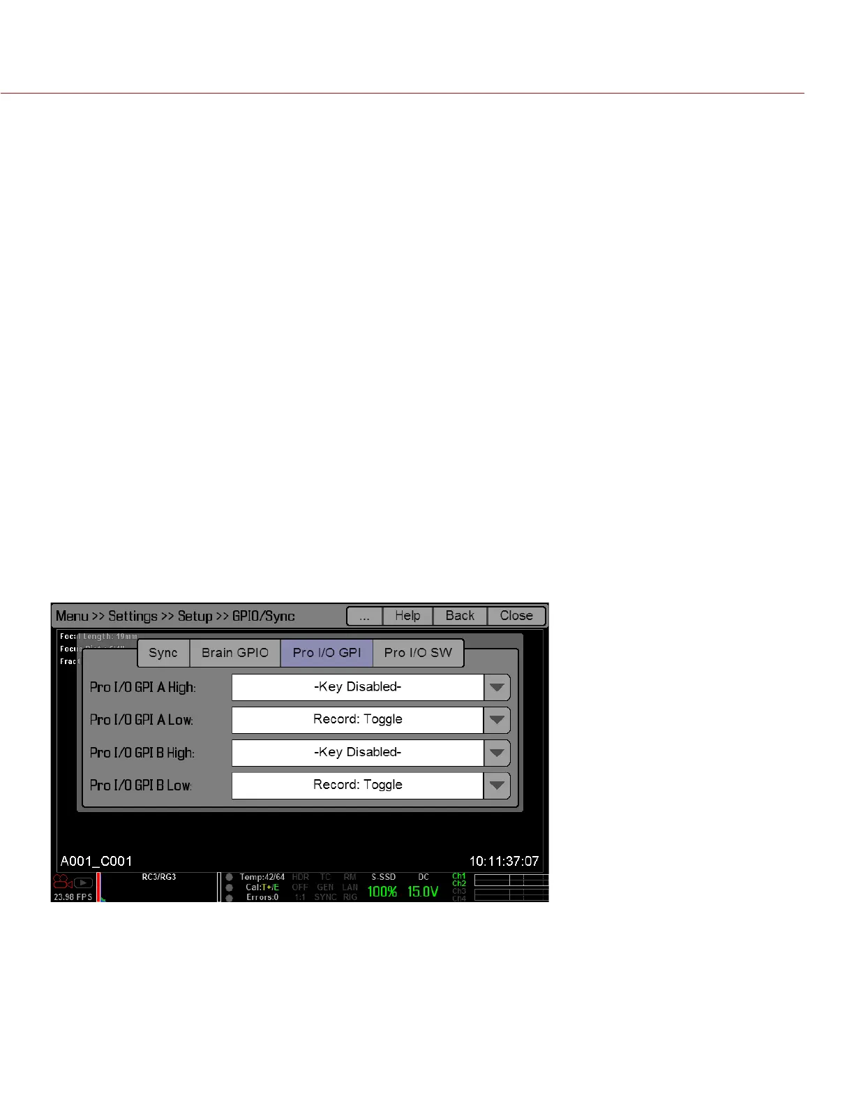
PRO I/O GPIO AND PRO I/O SW
Use the PRO I/O GPI and PRO I/O SW screens to assign General Purpose Inputs and Outputs (GPIO) on the
PRO I/O MODULE. You can map I/O actions to the GPIO and AUX connectors on the PRO I/O MODULE.
When mapping actions, High and Low refer to the voltage; High is the rising edge (transition from low voltage
to high voltage) and Low is the falling edge (transition from high voltage to low voltage). In practice, Low/High
correlates to the press/release of a trigger or the on/off position of a switch.
For example, if you connect a start/stop trigger to the GPIO connector on the PRO I/O MODULE and keep the
default GPIO A High and Low settings (Key Disabled and Record: Toggle, respectively), then pressing the trig-
ger starts/stops recording.