RED DSMC OPERATION GUIDE
COPYRIGHT © 2013 RED.COM, INC
955-0020_V5.1, REV-D | 81
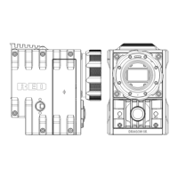
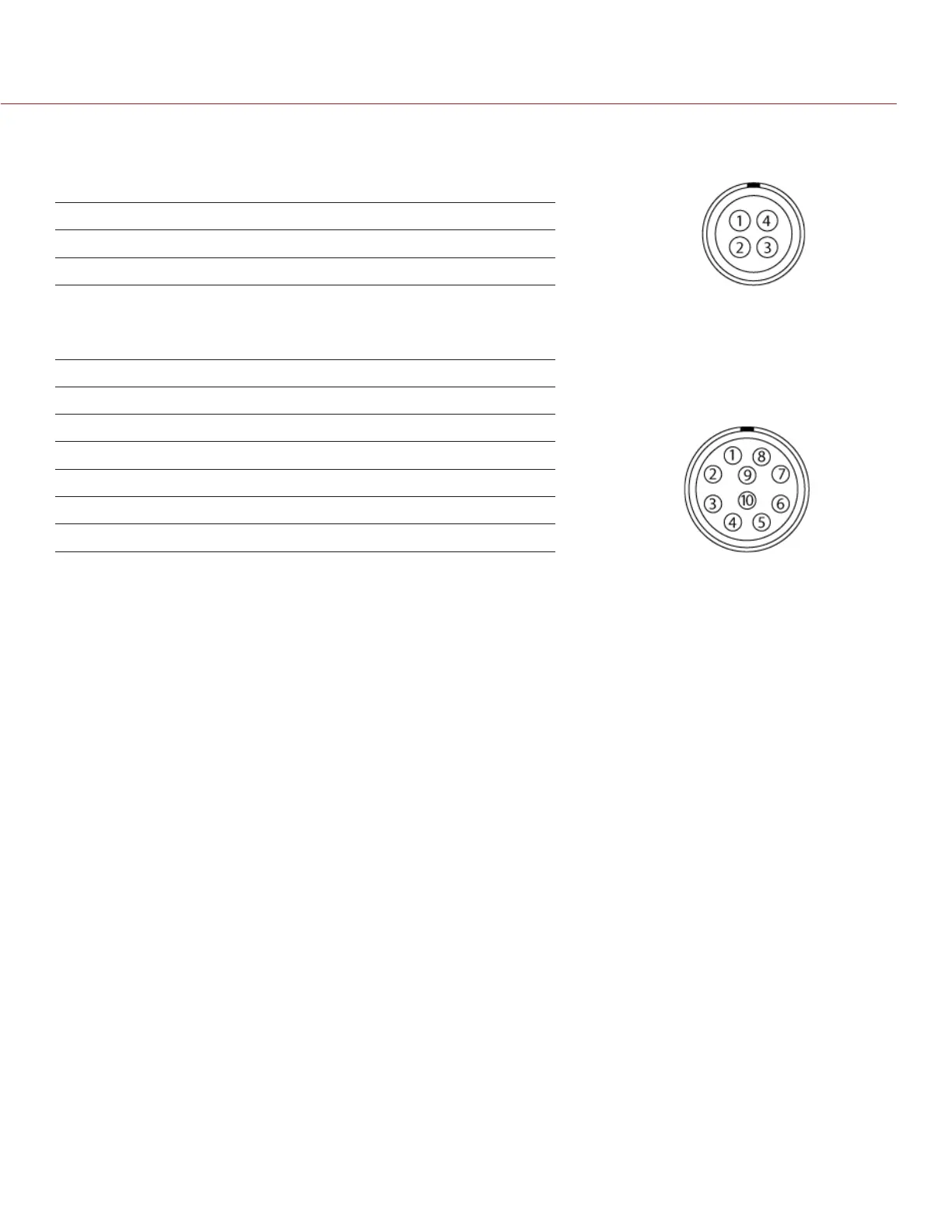
GPIO CONNECTOR
This table describes the I/O options for the GPIO connector on the PRO I/O MODULE:
I/O OPTION DEFAULT ACTION PIN
GPI A High Key Disabled 2
GPI A Low Record: Toggle 2
AUX CONNECTOR
This table describes the I/O options for the AUX connector on the PRO I/O MODULE:
I/O OPTION DEFAULT ACTION PIN
GPI B High Key Disabled 6
GPI B Low Record: Toggle 6
SW 1 High Key Disabled 7
SW 1 Low Go to: Playback 7
SW 2 High Key Disabled 5
SW 2 Low Record: Toggle 5
NOTE: For more information about the PRO I/O MODULE, see the PRO I/O Operation Guide available at www.
red.com/downloads.
FAN AND TEMPERATURE MANAGEMENT
Each RED DSMC is controlled by complex thermal algorithms to ensure that both the sensor and camera op-
erate at a safe temperature. Each fan control mode affects the sensor temperature, sensor warm-up time, fan
speed, and resulting fan noise.
When selecting a fan mode, RED recommends that you take into consideration how each fan mode behaves,
and then select a fan mode that fits the needs of your project.
Regardless of your sensor type and target temperature, you will get the best image quality by performing a
black shading calibration at the temperature you want to use for your shoot.
FAN CONTROL MODES
Select a fan control mode for your bottom fan. If a top fan is installed, it will activate at a constant speed when
necessary.
NOTE: If you select a new fan setting, run the DSMC until the core temperature stabilizes, and then perform a
black shading calibration.
NOTE: If you’re using a top fan, the top fan may not run immediately after turning on the DSMC, as the top fan
runs when the DSMC requires additional cooling power.
NOTE: Manual and Auto modes require that you actively manage the sensor temperature, because these modes
focus on controlling fan speed and do not target a narrow sensor temperature range. The T/E status icons can