3
Effective 06 2022 Drawing No. LP1133
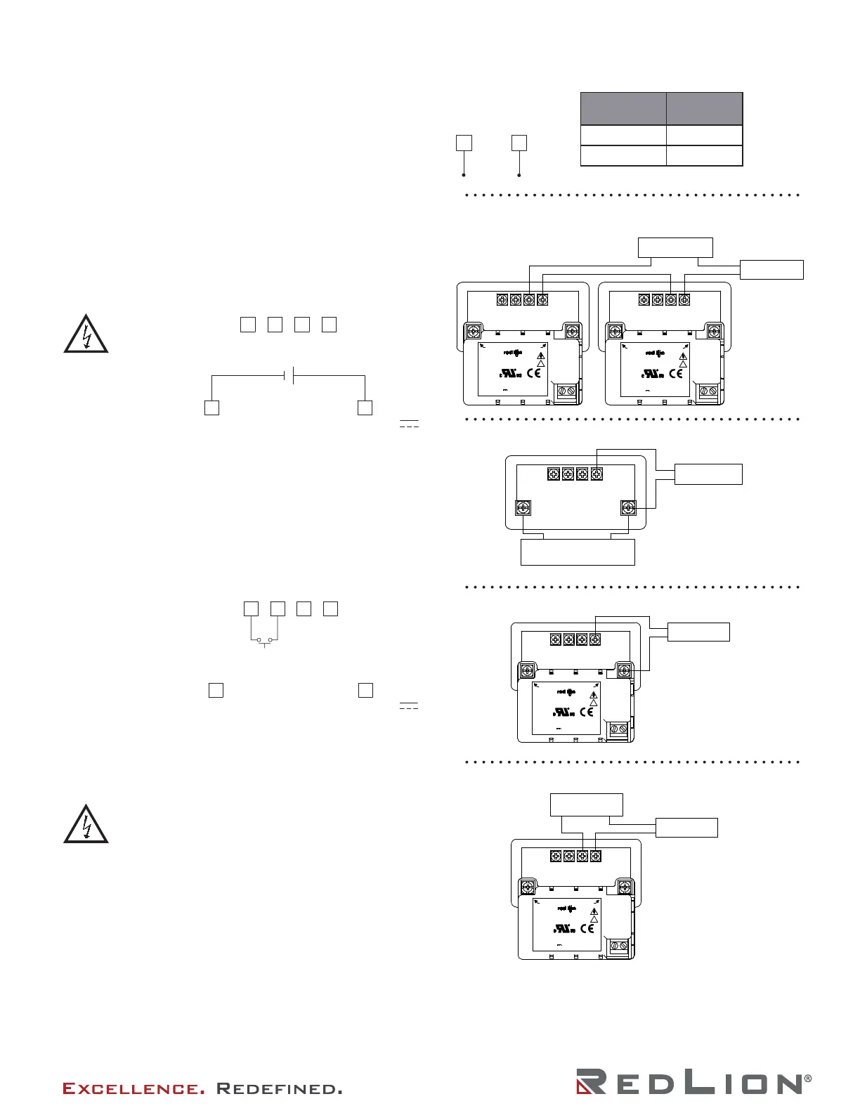
WIRING THE METER
Wiring Overview
Electrical connections are made via screw-clamp terminals
located on the back of the meter. All conductors should conform
to the meter’s voltage and current ratings. All cabling should
conform to appropriate standards of good installation, local codes
and regulations. It is recommended that the power supplied to
the meter (DC or AC) be protected by a fuse or circuit breaker.
Power Wiring
User Input Wiring
Input Wiring
CAUTION: Power input common is NOT isolated from
user and input commons. In order to preserve the safety
of the meter application, the power input common must
be suitably isolated from hazardous live earth referenced
voltage; or input common must be at protective earth ground
potential. If not, hazardous voltage may be present at the signal or
user inputs and input common terminals. Appropriate considerations
must then be given to the potential of the user and input commons
with respect to earth ground; and the common of the plug-in cards
with respect to input common.
Before connecting signal wires, the Input Range Jumper should be
verified for proper position.
Input Signal (self powered)
JUMPER
POSITION
MAX INPUT
CURRENT
10 VDC 30 VDC
20/50 mA DC 150 mA
Series Loop (must use separate supply for sensor power and
each CUB5)
2 Wire With External Power
2 Wire With MLPS Power Supply
2 Wire With Separate Sensor And CUB5 Power
USR COMM
USR
+9-28 VDC
COMM
INP +
PWR COMMON
+
-
DC Power
+9 to +28 VDC: +VDC
Power Common: -VDC
CAUTION: 9 to 28
VDC power circuit
is not isolated from
the signal circuit.
USR COMM
USR
+9-28 VDC
COMM
INP +
PWR COMMON
Sinking Logic
USR COMM
USR
The user input of the meter is
internally pulled up to +9 to
+28 V with 10 K resistance.
The input is active when it is
pulled low (<0 .7 V).
Connect external switching device between the
User Input terminal and User Input Common.
}
-
+
COMM
INP+
COMM
INP +
MODEL
INPUT POWER:
OUTPUT POWER:
85-250 VAC, 50/60Hz, 14VA
OPERATING TEMP: 0° TO 60°C
12VDC UNREG. @ 400mA
+12V
DC COMMON
M3424B
TERMINAL
AC INPUT
RED LION CONTROLS
YORK, PA. MADE IN U.S.A.
MLPS1
!
COMM
INP +
+VDC
COMM
EXTERNAL POWER
2 WIRE TRANSMITTER
+
_
MODEL
INPUT POWER:
OUTPUT POWER:
85-250 VAC, 50/60Hz, 14VA
OPERATING TEMP: 0° TO 60°C
12VDC UNREG. @ 400mA
+12V
DC COMMON
M3424B
TERMINAL
AC INPUT
RED LION CONTROLS
YORK, PA. MADE IN U.S.A.
MLPS1
!
JUMPER
POSITION
20/50 mA DC
2 WIRE TRANSMITTER
INP +
COMM
EXTERNAL POWER
COMM
COMM
+VDC
+VDC
_
+
JUMPER
POSITION
20/50 mA DC
2 WIRE TRANSMITTER
COMM
INP +
_
+
MODEL
INPUT POWER:
OUTPUT POWER:
85-250 VAC, 50/60Hz, 14VA
OPERATING TEMP: 0° TO 60°C
12VDC UNREG. @ 400mA
+12V
DC COMMON
M3424B
TERMINAL
AC INPUT
RED LION CONTROLS
YORK, PA. MADE IN U.S.A.
MLPS1
!
JUMPER
POSITION
20/50 mA DC
2 WIRE TRANSMITTER
INP +
COMM
EXTERNAL POWER
COMM
+VDC
+
_
MODEL
INPUT POWER:
OUTPUT POWER:
85-250 VAC, 50/60Hz, 14VA
OPERATING TEMP: 0° TO 60°C
12VDC UNREG. @ 400mA
+12V
DC COMMON
M3424B
TERMINAL
AC INPUT
RED LION CONTROLS
YORK, PA. MADE IN U.S.A.
MLPS1
!
JUMPER
POSITION
20/50 mA DC

 Loading...