10
INSTALLATION
The unit is equipped with a universal mounting foot for attachment to standard DIN style mounting rails, including G profile rail
according to EN50035 - G32 , and top hat (T) profile rail according to EN50022 - 35 x 7.5 and - 35 x 15. The unit should be installed in a
location that does not exceed the maximum operating temperature and provides good air circulation. Placing the unit near devices that
generate excessive heat should be avoided.
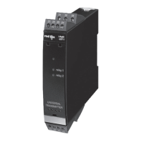
G Rail Installation
To install the IAMS on a “G”
style DIN rail, angle the module
so that the upper groove of the
“foot” catches under the lip of the
top rail. Push the module toward
the rail until it snaps into place.
To remove a module from the
rail, push up on the bottom of the
module while pulling out and
away from the rail.
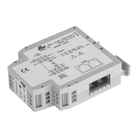
T Rail Installation
To install the IAMS on a “T”
style rail, angle the module so
that the top groove of the “foot”
is located over the lip of the top
rail. Push the module toward the
rail until it snaps into place. To
remove a module from the rail,
insert a screwdriver into the slot
on the bottom of the “foot”, and
pry upwards on the module until
it releases from the rail.
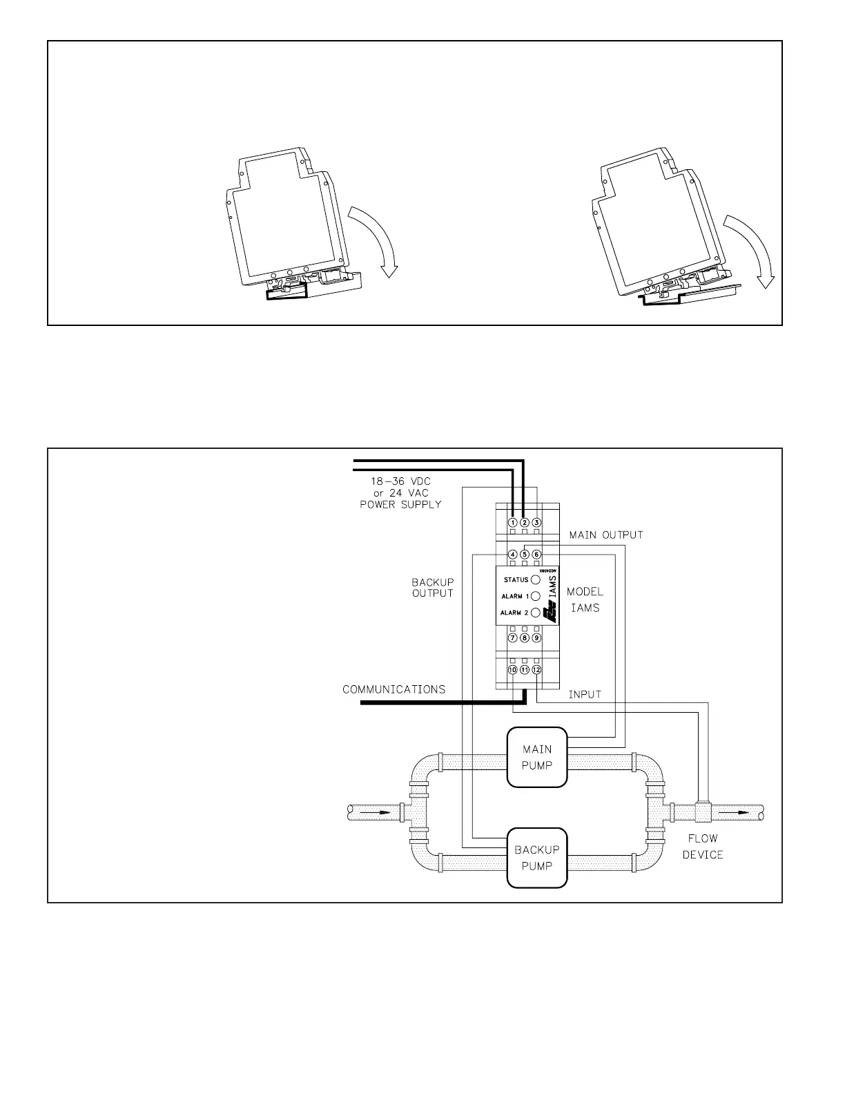
APPLICATION
Untreated waste needed to be pumped up a hill to a treatment
center. To prevent undesirable shut downs, a backup pump and
a flow transducer were installed in the line. The operator
needed the ability to monitor the flow, as well as the ability to
change setpoints from the main station, located 4000 feet away.
The temperature within the pumping station was not controlled.
The IAMS was installed because of the size, operating
temperature range, serial communications, and the ability to
control the pumps. When the flow is below a certain level, the
IAMS switches the Main Pump off, and the Backup Pump on.
Operators can monitor the flow and change the setpoints from
the main building using a PC acquisition program with a
MODBUS driver.
 Loading...