3
WIRING CONNECTIONS
All conductors should meet voltage and current ratings for each terminal.
Also, cabling should conform to appropriate standards of good installation,
local codes and regulations. When wiring the module, use the numbers on the
label to identify the position number with the proper function. Strip the wire,
leaving approximately 1/4" (6 mm) of bare wire exposed. Insert the wire into
the terminal, and tighten the screw until the wire is clamped tightly. (Pull wire
to verify tightness.) Each terminal can accept up to one #14 AWG (2.55 mm),
two #18 AWG (1.02 mm), or four #20 AWG (0.61 mm) wires.
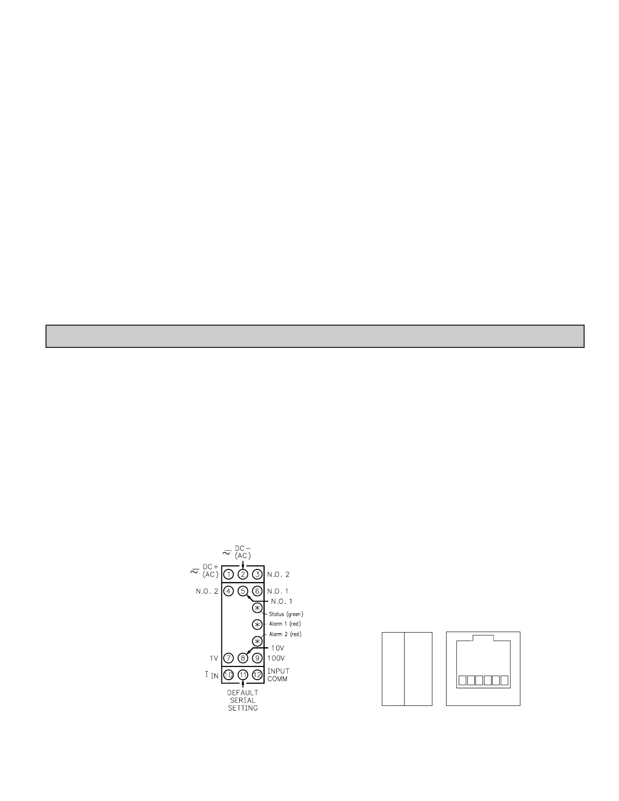
MODULE POWER CONNECTIONS
Module power is connected to terminals 1 and 2. For best results, the power
should be relatively “clean” and within the specified limits. Drawing power
from heavily loaded circuits or from circuits that also power loads that cycle on
and off should be avoided. It is recommended that power supplied to the module
be protected by a fuse or circuit breaker.
INPUT CONNECTIONS
Current Input
Wiring for a current input is
connected to terminals 10 (+) and 12 (-).
Terminal 10 (+): 100 mA
Voltage Input
Wiring for a voltage input is
connected to terminal 12 (-) and one of
the voltage terminals listed below.
Terminal 7 (+): 1 VDC max.
Terminal 8 (+): 10 VDC max.
Terminal 9 (+): 100 VDC max.
RELAY OUTPUT CONNECTIONS
There are two Form A output relays. The wiring for Relay 1 is connected
between terminals 5 and 6. The wiring for Relay 2 is connected between
terminals 3 and 4.
To prolong contact life and suppress electrical noise interference due to the
switching of inductive loads, it is good installation practice to install a snubber
across the contactor. Follow the manufacturer’s instructions for installation.
Note: Snubber leakage current can cause some high impedance loads to be held
ON.
DEFAULT SERIAL SETTING CONNECTION
If the IAMS settings are unknown, or forgotten, they can be reset to the
factory defaults by connecting the Serial Default terminal 11 to Input Comm.
terminal 12 with a jumper, and then cycling power.
DEFAULTS:
RS485 SERIAL CONNECTIONS
There are two RJ-11 connectors located on the bottom for paralleling
communications. For single device communications, either connector can be
used. When used in conjunction with Red Lion Control Paradigm HMI
products, reverse A+ and B- wiring.
STEP 1 WIRING THE MODULE
Protocol: RTU
Address: 247
Baud Rate: 9600
Data Bits:
Parity:
8
none
Although this unit is designed with a high degree of immunity to Electro-
Magnetic Interference (EMI), proper installation and wiring methods must be
followed to ensure compatibility in each application. The type of the electrical
noise, source or coupling method into the unit may be different for various
installations. Cable length, routing, and shield termination are very important
and can mean the difference between a successful or troublesome installation.
Listed below are some EMC guidelines for successful installation in an
industrial environment.
1. Use shielded (screened) cables for all Signal and Control inputs. The shield
(screen) pigtail connection should be made as short as possible. The
connection point for the shield depends somewhat upon the application.
Listed below are the recommended methods of connecting the shield, in order
of their effectiveness.
a. Connect the shield only at the rail where the unit is mounted to earth
ground (protective earth).
b. Connect the shield to earth ground at both ends of the cable, usually when
the noise source frequency is above 1 MHz.
c. Connect the shield to common of the unit and leave the other end of the
shield unconnected and insulated from earth ground.
2. Never run Signal or Control cables in the same conduit or raceway with AC
power lines, conductors feeding motors, solenoids, SCR controls, and
heaters, etc. The cables should be run in metal conduit that is properly
grounded. This is especially useful in applications where cable runs are long
and portable two-way radios are used in close proximity or if the installation
is near a commercial radio transmitter.
3. Signal or Control cables within an enclosure should be routed as far away as
possible from contactors, control relays, transformers, and other noisy
components.
4. In extremely high EMI environments, the use of external EMI suppression
devices, such as ferrite suppression cores, is effective. Install them on Signal
and Control cables as close to the unit as possible. Loop the cable through the
core several times or use multiple cores on each cable for additional
protection. Install line filters on the power input cable to the unit to suppress
power line interference. Install them near the power entry point of the
enclosure. The following EMI suppression devices (or equivalent) are
recommended:
Ferrite Suppression Cores for signal and control cables:
Fair-Rite # 0443167251 (RLC # FCOR0000)
TDK # ZCAT3035-1330A
Steward # 28B2029-0A0
Line Filters for input power cables:
Schaffner # FN610-1/07 (RLC # LFIL0000)
Schaffner # FN670-1.8/07
Corcom # 1 VR3
Note: Reference manufacturer’s instructions when installing a line filter.
5. Long cable runs are more susceptible to EMI pickup than short cable runs.
Therefore, keep cable runs as short as possible.
EMC INSTALLATION GUIDELINES
 Loading...