8
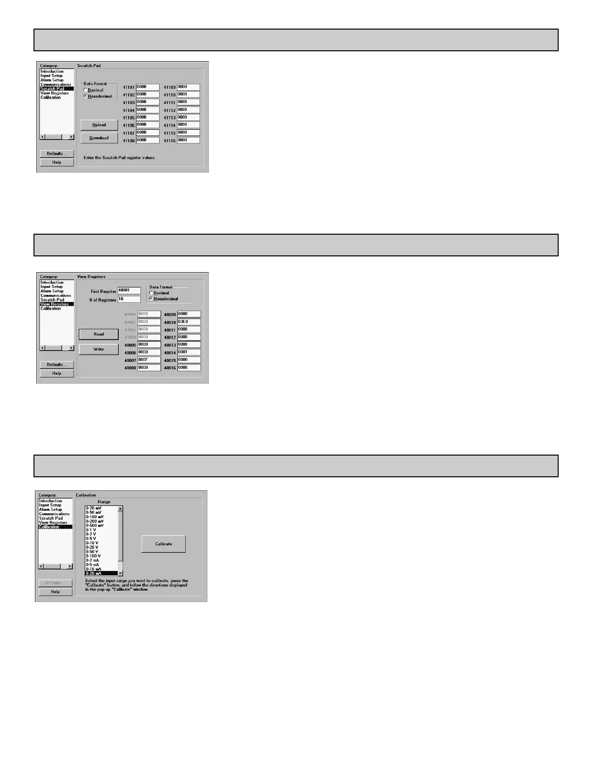
The IAMS is fully calibrated from the factory. Voltage or Current range calibration is recommended
every two years. Internal ADC calibration is not recommended unless the voltage or current values are
still incorrect after their calibration. If the ADC calibration is performed, the voltage or current
calibration must be performed. Each input range has its’ own minimum and maximum ADC references
(registers 40005 and 40006) which are recalled when the range is selected. This allows independent
calibration for the desired range. Calibration may be performed via MODBUS commands, or by using
SFIMS software.
Allow the IAMS to warm up for 30 minutes minimum, and follow the manufacturer’s warm-up
procedure for the calibration source.
Note: Calibration requires a precision signal source with an accuracy of 0.025%, and must be capable
of generating the full span of the range to be calibrated. When using SFIMS for calibration, connect
the signal source to the IAMS, select the proper range in the software, and press the Calibrate button.
Follow the calibration procedures in the software.
STEP 11 CALIBRATION
STEP 9 SCRATCH PAD MEMORY
STEP 10 VIEW REGISTERS
The Scratch Pad category can be used to read or write to the Scratch Pad memory locations (41101-
41116). The Scratch Pad locations can be used to store user information.
Data Format: Allows registers to be viewed in decimal or hexadecimal format.
Upload: The Upload button causes SFIMS software to read the Scratch Pad registers from the module.
Download: The Download button causes SFIMS software to write to the Scratch Pad registers in the
module.
Note: Downloading new values to the module Scratch Pad locations overwrites the information that is
currently stored in those registers.
The View Registers category can be used as a method of diagnostics. Use the IAMS Register Table
as a reference of register assignments and data.
First Register: This specifies the first, or only, register to be read in a block.
# of Registers: This is the length of the block to be read. The module supports block read and write
commands up to 16 registers in length.
Data Format: Allows registers to be viewed in decimal or hexadecimal format.
Read: Clicking the Read button causes SFIMS software to read the selected register from the module.
Write: Clicking the Write button causes SFIMS software to write the selected registers to the module.
Note: The Write button overwrites the existing register values, and may change the module setup and
operation.
 Loading...