2
8. SERIAL COMMUNICATIONS:
Type: RS485, MODBUS RTU and ASCII modes
Baud: 300, 600, 1200, 2400, 4800, 9600, 19.2K, and 38.4K
Format: 7/8 bit, odd, even and no parity
Transmit Delay: Programmable. (See Transmit Delay explanation in Step 6)
Transmit Enable (TXEN): (primarily for 20 mA loop converter)
V
OH
= 10 VDC max. V
OL
= 0.5 VDC @ 5 mA max. current limit
9. A/D CONVERTER: 16 bit resolution
10. ACCURACY (including linearity): 0.1% of span
11. RESOLUTION: 0.002% of span
12. GAIN / OFFSET: Programmable
13. RELAY OUTPUTS:
Type: 2 Form A N.O. contacts
Rating: 5A @ 30 VDC or 250 VAC max. (resistive)
1/10 HP @ 120 VAC (inductive)
Response Time: 155 msec. max. to close including step response, 153 msec.
max. to open.
14. OUTPUT ON DELAY TIME: Programmable from 0 to 32000 sec,
±0.01% - 1 sec. max.
15. MEMORY: Nonvolatile E
2
PROM retains all programmable parameters.
16. ENVIRONMENTAL CONDITIONS:
Operating Temperature Range: -20 to +65 GC
Storage Temperature Range: -40 to +85 GC
Operating and Storage Humidity: 85% max. relative humidity (non-
condensing) from -20 to +65 GC
Temperature Coefficient: +0.01%/ GC (100 PPM GC) max.
Altitude: Up to 2000 meters
17. CERTIFICATIONS AND COMPLIANCE:
SAFETY
UL Recognized Component, File # E179259, UL3101-1, CSA 22.2 No. 1010-1
Recognized to U.S. and Canadian requirements under the Component
Recognition Program of Underwriters Laboratories, Inc.
IECEE CB Scheme Test Certificate # US/5141A/UL,
CB Scheme Test Report # 01ME11540-0702001
Issued by Underwriters Laboratories, Inc.
IEC 1010-1, EN 61010-1: Safety requirements for electrical equipment
for measurement, control, and laboratory use, Part 1.
ELECTROMAGNETIC COMPATIBILITY
Notes:
1. This device was designed for installation in an enclosure. To avoid
electrostatic discharge to the module in environments with static levels
above 6 KV, precautions should be taken when the device is mounted
outside an enclosure. When working in an enclosure (ex. making
connections, etc.), typical anti-static precautions should be observed
before touching the module.
Refer to the EMC Installation Guidelines section of this bulletin for
additional information.
18. CONSTRUCTION: Case body is green high impact plastic. Installation
Category II, Pollution Degree 2.
19. CONNECTIONS: 14 AWG max.
20. MOUNTING: Universal mounting foot for attachment to standard DIN
style mounting rails, including top hat (T) profile rail according to EN50022
- 35 x 7.5 and - 35 x 15, and G profile rail according to EN50035 - G32.
21. WEIGHT: 4.5 oz. (127.57 g)
MODULE ISOLATION
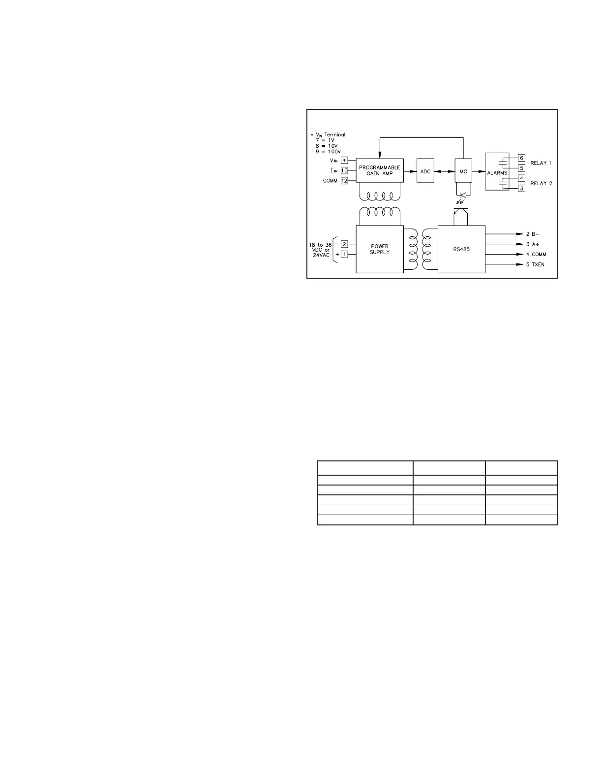
The IAMS features “4-way” signal isolation. The 4-way isolation is a
combination of optical, transformer and relay barriers, providing common mode
voltage (CMV) isolation to 1.5 KV for 1 minute between input, RS485, and
power supply. Isolation between relay contacts and all other inputs is 2300 Vrms
for 1 minute.
LED FUNCTIONALITY
Power mains class A
Enclosure class AEN 55011RF interference
Emissions to EN 55011
Level 3; 10 V/mENV 50204Simulation of cordless telephone
150 KHz - 80 MHz
Level 3; 10 V/rms EN 61000-4-6RF conducted interference
Level 3; 2 KV power
Level 4; 2 KV I/O EN 61000-4-4Fast transients (burst)
80 MHz - 1 GHz
Level 3; 10 V/MEN 61000-4-3Electromagnetic RF fields
Level 3; 8 KV air
1
Level 2; 4 KV contact EN 61000-4-2Electrostatic discharge
200 Hz, 50% duty cycle
Immunity to EN 50082-2
900 MHz ± 5 MHz
CONDITION GREEN LED 2 RED LEDS
Power Applied On ———
Communication Received Flashing ———
Respective Alarm ——— On
Checksum error Flashing Flashing
Calibration Off On
BLOCK DIAGRAM
 Loading...