EasyManua.ls Logo

red lion IAMS - User Manual

red lion IAMS
16 pages
Print Icon
To Next Page IconTo Next Page
Loading...
GENERAL DESCRIPTION
The IAMS3535 Smart Analog to MODBUS Conditioner with Alarms
module accepts a wide range of DC analog process signals. There are eighteen
different DC analog input ranges which determine the input span and type. The
input accepts a maximum of 110 VDC and 110 mA DC.
The IAMS converts an analog input signal into a register format that can be
read using ASCII or RTU MODBUS protocol. With the features of gain and
offset, the input signal can be scaled to meet process requirements. Additionally,
two setpoint values can be entered for dual relay process monitoring alarms.
The IAMS is programmed with Windows™ based SFIMS software. The
software allows configuration, calibration, and storage of IAMS program files.
Additionally, all setup parameters can be interrogated and modified through
MODBUS register and coil commands.
The RS485 port allows the IAMS to be multidropped, with Baud rates up to
38400. The CBPRO007 programming cable converts the RS232 port of a PC to
RS485, and is terminated with an RJ-11 connector. The bidirectional capability
of the CBPRO007 allows it to be used as a permanent interface cable as well as
a programming cable.
The IAMS’s two Form A relay alarms can be configured independently for
absolute high or low acting with balanced or unbalanced hysteresis. Alarm 2 can
also be configured for deviation and band alarms. In these modes, Setpoint 2
tracks Setpoint 1. Adjustable alarm trip delays can be used for delaying output
response. The alarms can be programmed for Automatic or Latching. Latched
alarms must be reset via serial command. A standby feature supresses the alarm
during power-up until the process stabilizes outside the alarm region. Standby
eliminates power-up tripping for low acting alarms. The output relays can also
be manually controlled via register commands.
The module’s high density packaging and DIN rail mounting saves time and
panel space. The module is equipped with a universal mounting foot for
attachment to standard DIN rails, including top hat (T) profile or G profile rail.
SAFETY SUMMARY
All safety related regulations, local codes and instructions that appear in the
manual or on equipment must be observed to ensure personal safety and to
prevent damage to either the instrument or equipment connected to it. If
equipment is used in a manner not specified by the manufacturer, the protection
provided by the equipment may be impaired.
ORDERING INFORMATION
SPECIFICATIONS
1. POWER: 18-36 VDC, 3.0 W max. or 24 VAC, ± 10%, 50/60 Hz, 4 VA max.
2. INPUT DC RANGES:
0-20 mV, 0-50 mV, 0-100 mV, 0-200 mV, 0-500 mV, 0-1V, 0-2 V, 0-5 V,
0-10 V, 0-20 V, 0-50 V, 0-100 V, 0-2 mA, 0-5 mA, 0-10 mA, 0-20 mA,
0-50 mA, 0-100 mA
3. MAX. INPUT SIGNAL:
Current Input: 110 mA DC
Voltage Inputs: Terminal 7: 1 VDC +10%
Terminal 8: 10 VDC +10%
Terminal 9: 100 VDC +10%
4. INPUT RESISTANCE:
Current: 10 Ohms
Voltage: greater than 100 K
5. INPUT PROTECTION: Surge suppressor diode
Current Terminal: Protected to 110 mA DC max., 1.1 VDC.
100 V Terminal: Protected to 110 VDC.
1 V & 10 V Terminal: Protected to 100 VDC for one minute.
6. INPUT COMMON MODE REJECTION: 50/60 Hz, 110 dB min.
7. ISOLATION LEVEL: 1.5 kV @ 50/60 Hz, 1 min. between input, RS485
and power supply. 2300 Vrms, 1 min. to relay contacts.
1
O
ANALOG TO MODBUS CONVERSION
O
18 DIFFERENT DC ANALOG INPUT RANGES
O
PROCESSOR BASED SCALING
O
PC CONFIGURATION SOFTWARE
O
DUAL SETPOINT RELAY ALARMS
O
FOUR WAY SIGNAL ISOLATION
MODEL IAMS - INTELLIGENT ANALOG TO MODBUS CONDITIONER W/ ALARMS
MODEL
IAMS
DESCRIPTION
Smart Analog to Modbus Conditioner w/Alarms
PART NUMBER
IAMS3535
CBPRO
SFIMS
Programming Interface Cable
PC Configuration Software for Windows
CBPRO007
SFIMS
-
CBJ
RJ11 to Terminal Adapter
Cable RJ11 to Unterminated 7 foot length
DRRJ11T6
CBJ11A07
Cable RJ11 to RJ11 6 inch jumper CBJ11BD5
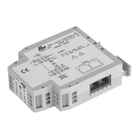
DIMENSIONS In inches (mm)
CAUTION: Read complete
instructions prior to installation
and operation of the unit.
CAUTION: Risk of electric shock.
Bulletin No. IAMS-A
Drawing No. LP0475
Released 9/01
Tel +1 (717) 767-6511
Fax +1 (717) 764-0839
www.redlion-controls.com
UL Recognized Component,
File # E179259

Questions and Answers

  • M
    medinajoshuaJul 28, 2025
    How to fix Red Lion Test Equipment that will not communicate?
    • K
      Kevin WilliamsJul 28, 2025
      If your Red Lion Test Equipment won't communicate, there are several things to check: * Verify the IAMS communications setup for incorrect serial settings on the IAMS port. * Check the PC port settings under the SETTINGS pull-down menu for incorrect serial settings on the computer port. * If the wiring is incorrect, try switching A+ and B- lines or provide a common connection.
  • T
    Thomas TaylorAug 2, 2025
    Why is the process value not changing or incorrect on my Red Lion Test Equipment?
    • B
      Brooke CookeAug 2, 2025
      If the process value on your Red Lion Test Equipment is not changing or is incorrect, the cause may be incorrect scaling. To resolve this, check the input setup and scaling values, then re-download the configuration.
  • U
    udelacruzAug 7, 2025
    What to do if the process value stays at 32002 or -32002 on Red Lion Test Equipment?
    • H
      Heather LivingstonAug 7, 2025
      If the process value remains at 32002 or -32002 on your Red Lion Test Equipment, it may be due to ADC over range caused by an incorrect input signal, incorrect input setup, or improper calibration. First, check the input signal connections and level. If the issue persists, check the Input Setup and re-download. If problems continue, perform the calibration procedure.
  • R
    Ryan AbbottAug 12, 2025
    Why does the process value stay at 32001 or -32001 on my Red Lion Test Equipment?
    • C
      Charles MasonAug 12, 2025
      If the process value remains at 32001 or -32001 on your Red Lion Test Equipment, it could be due to gain/offset over range caused by an incorrect input signal or incorrect input setup scaling. Check the input signal connections and level. Also, check the Input setup, and re-download.
  • A
    Andrew McclureAug 17, 2025
    What does it mean when LEDs are flashing and alarms are disabled on Red Lion Test Equipment?
    • J
      john69Aug 17, 2025
      Flashing LEDs and disabled alarms on your Red Lion Test Equipment can indicate a parameter checksum error or loss of parameter settings. To resolve this, re-download the SFIMS file, which reconfigures each parameter. If the problem persists, it may be due to a calibration checksum error, requiring you to perform the calibration procedure.
  • T
    Todd RoyAug 22, 2025
    How to troubleshoot if the green LED will not light on Red Lion Test Equipment?
    • K
      Kyle LarsenAug 22, 2025
      If the green LED on your Red Lion Test Equipment does not light up, the issue is likely related to module power. Verify the module power connections and level.

Summary

General Description and Safety

General Description

Detailed explanation of the IAMS3535 Smart Analog to MODBUS Conditioner functionality and features.

Product Information

Specifications

Technical data, input/output ranges, electrical ratings, and environmental conditions.

EMC Installation Guidelines

Wiring the Module

Software Installation and Setup

Installing SFIMS Software

Instructions for installing the SFIMS configuration software.

Programming the Input

Gain and Offset Calculation

Using the Scaling Wizard to determine gain and offset values for scaling.

Programming the Alarms

Setpoint and Hysteresis

How to configure alarm setpoints and hysteresis for stable output.

Programming the Comms Port

Modbus Protocol Settings

Configuring Modbus protocol, unit address, baud rate, data bits, and parity.

PC Port Configuration

Communications Settings

Setting up the PC communication port (COM) for device interaction.

Downloading Data

Calibration Procedures

ADC Calibration

Step-by-step guide for calibrating the Analog-to-Digital Converter.

Voltage or Current Calibration

Detailed steps for calibrating voltage and current input ranges.

Troubleshooting Common Issues

Modbus Communication Details

Calibration Procedures (Modbus)

Register and Coil Tables

Register Table Description

Details of holding/input registers, addresses, limits, and access.

Register Tables (Detailed)

red lion IAMS Specifications

General IconGeneral
Brandred lion
ModelIAMS
CategoryTest Equipment
LanguageEnglish

Related product manuals