27
COMMUNICATION FORMAT
Data is transferred from the meter through a serial communication channel.
In serial communications, the voltage is switched between a high and low level
at a predetermined rate (baud rate) using ASCII encoding. The receiving device
reads the voltage levels at the same intervals and then translates the switched
levels back to a character.
The voltage level conventions depend on the interface standard. The table
lists the voltage levels for each standard.
Data is transmitted one byte at a time with a variable idle period between
characters (0 to ∞). Each ASCII character is “framed” with a beginning start bit,
an optional parity bit and one or more ending stop bits. The data format and
baud rate must match that of other equipment in order for communication to
take place. The figures list the data formats employed by the meter.
Start bit and Data bits
Data transmission always begins with the start bit. The start bit signals the
receiving device to prepare for reception of data. One bit period later, the least
significant bit of the ASCII encoded character is transmitted, followed by the
remaining data bits. The receiving device then reads each bit position as they are
transmitted.
Parity bit
After the data bits, the parity bit is sent. The transmitter sets the parity bit to
a zero or a one, so that the total number of ones contained in the transmission
(including the parity bit) is either even or odd. This bit is used by the receiver
to detect errors that may occur to an odd number of bits in the transmission.
However, a single parity bit cannot detect errors that may occur to an even
number of bits. Given this limitation, the parity bit is often ignored by the
receiving device. The PAX meter ignores the parity bit of incoming data and
sets the parity bit to odd, even or none (mark parity) for outgoing data.
Stop bit
The last character transmitted is the stop bit. The stop bit provides a single bit
period pause to allow the receiver to prepare to re-synchronize to the start of a
new transmission (start bit of next byte). The receiver then continuously looks
for the occurrence of the start bit. If 7 data bits and no parity is selected, then 2
stop bits are sent from the PAXI.
Character Frame Figure
LOGIC RS232* RS485*INTERFACE STATE
1 TXD,RXD; -3 to -15 V a-b < -200 mVmark (idle)
0 TXD,RXD; +3 to +15 V a-b > +200 mVspace (active)
* Voltage levels at the Receiver
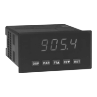
COMMAND RESPONSE TIME
The meter can only receive data or transmit data at any one time (half-duplex
operation). During RS232 transmissions, the meter ignores commands while
transmitting data, but instead uses RXD as a busy signal. When sending
commands and data to the meter, a delay must be imposed before sending
another command. This allows enough time for the meter to process the
command and prepare for the next command.
At the start of the time interval t
1
, the computer program prints or writes the
string to the com port, thus initiating a transmission. During t
1
, the command
characters are under transmission and at the end of this period, the command
terminating character (*, $ or slave only <CR>) is received by the meter. The
time duration of t
1
is dependent on the number of characters and baud rate of
the channel.
t
1
= (10 times the # of characters) / baud rate
At the start of time interval t
2
, the meter starts the interpretation of the
command and when complete, performs the command function. This time
interval t
2
varies from 2 msec to 15 msec. If no response from the meter is
expected, the meter is ready to accept another command.
If the meter is to reply with data, the time interval t
2
is controlled by the use
of the command terminating character and the Serial Transmit Delay parameter
(dELAY). The ‘*’ or ‘<CR>’ terminating character results in a response time
window of the Serial Transmit Delay time (dELAY) plus 15 msec. maximum. The
dELAY parameter should be programmed to a value that allows sufficient time for
the release of the sending driver on the RS485 bus. Terminating the command
line with “$” results in a response time window (t
2
) of 2 msec minimum and 15
msec maximum. The response time of this terminating character requires that
sending drivers release within 2 msec after the terminating character is
received.
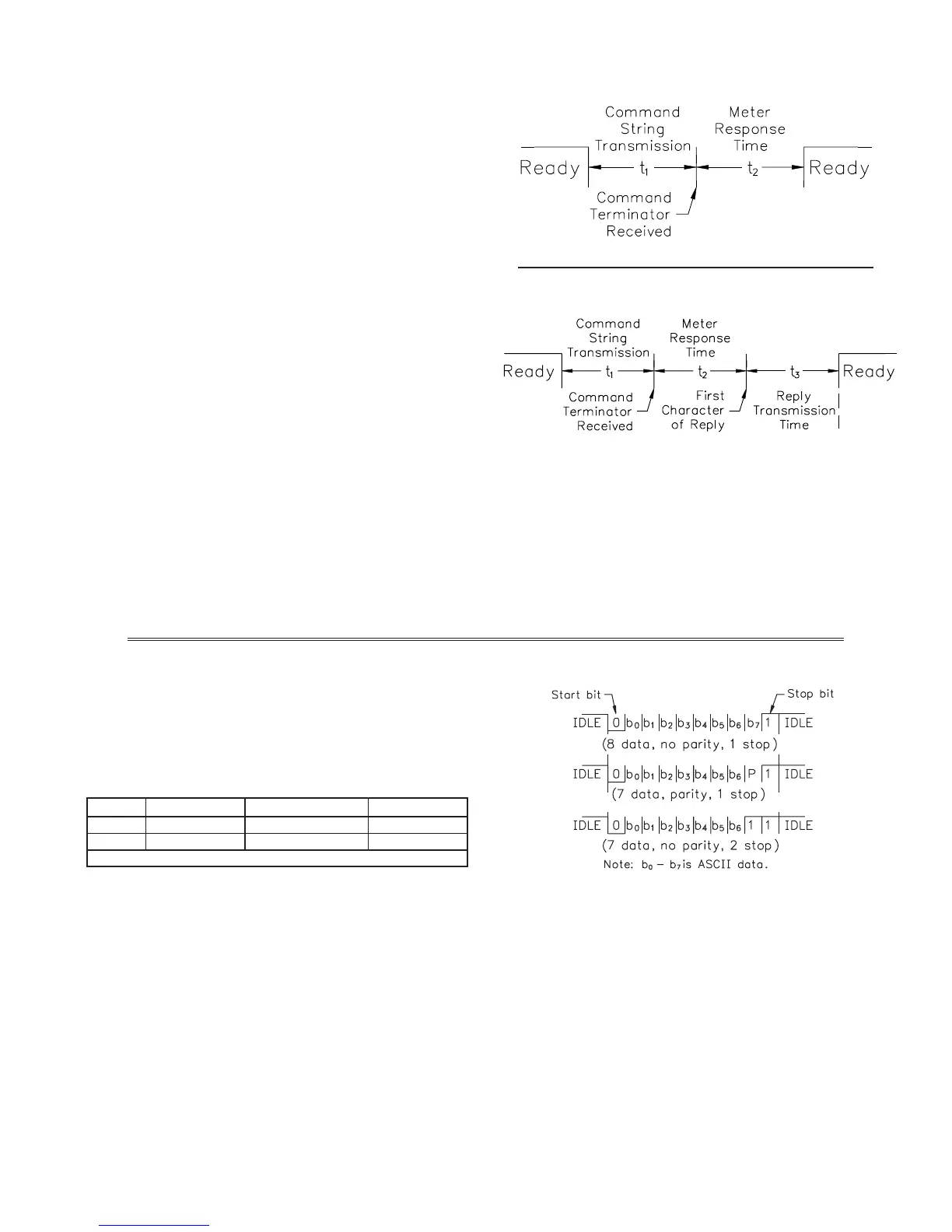
At the beginning of time interval t
3
, the meter responds with the first
character of the reply. As with t
1
, the time duration of t
3
is dependent on the
number of characters and baud rate of the channel. At the end of t
3
, the meter is
ready to receive the next command.
t
3
= (10 times the # of characters) / baud rate
The maximum serial throughput of the meter is limited to the sum of the
times t
1
, t
2
and t
3
.
NO REPLY FROM METER
RESPONSE FROM METER
Timing Diagrams

 Loading...