8
The Plug-in cards are separately purchased optional cards that perform
specific functions. These cards plug into the main circuit board of the meter. The
Plug-in cards have many unique functions when used with the PAX.
Note: The PAXC and PAXR only use the setpoint option card.
CAUTION: The Plug-in card and main circuit board contain static sensitive
components. Before handling the cards, discharge static charges
from your body by touching a grounded bare metal object. Ideally,
handle the cards at a static controlled clean workstation. Also, only
handle the cards by the edges. Dirt, oil or other contaminants that
may contact the cards can adversely affect circuit operation.
To Install:
1. With the case open, locate the Plug-in card connector for the card type to be
installed. The types are keyed by position with different main circuit board
connector locations. When installing the card, hold the meter by the rear
terminals and not by the front display board.*
2. Install the Plug-in card by aligning the card terminals with the slot bay in the
rear cover. Be sure the connector is fully engaged and the tab on the Plug-in
card rests in the alignment slot on the display board.
3. Slide the meter base back into the case. Be sure the rear cover latches fully
into the case.
4. Apply the Plug-in card label to the bottom side of the meter in the designated
area. Do Not Cover the vents on the top surface of the meter. The surface of
the case must be clean for the label to adhere properly.
3.0 insTalling plug-in Cards
(18 V unregulated)
External Supply
(30 V )
max
Quad Sourcing Open Collector Output Card Supply Select
* If installing the Quad sourcing Plug-in Card (PAXCDS40), set the
jumper for internal or external supply operation before continuing.
Finger
Hold
Finger
Hold
Serial
Communications
Card
Setpoint
Output
Card
Alignment
Slots
Connectors
Analog Output
Card
Main
Circuit
Board
TOP VIEW
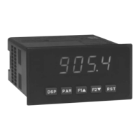
2.0 seTTing The Jumper and dip swiTChes
2.1 SETTING THE JUMPER
The meter has one jumper for user input logic. When using the user inputs
this jumper must be set before applying power. The Main Circuit Board figure
shows the location of the jumper and DIP switch.
The user input jumper determines signal logic for the user inputs, when they
are used with user functions or for input signal direction. All user inputs are set
by this jumper.
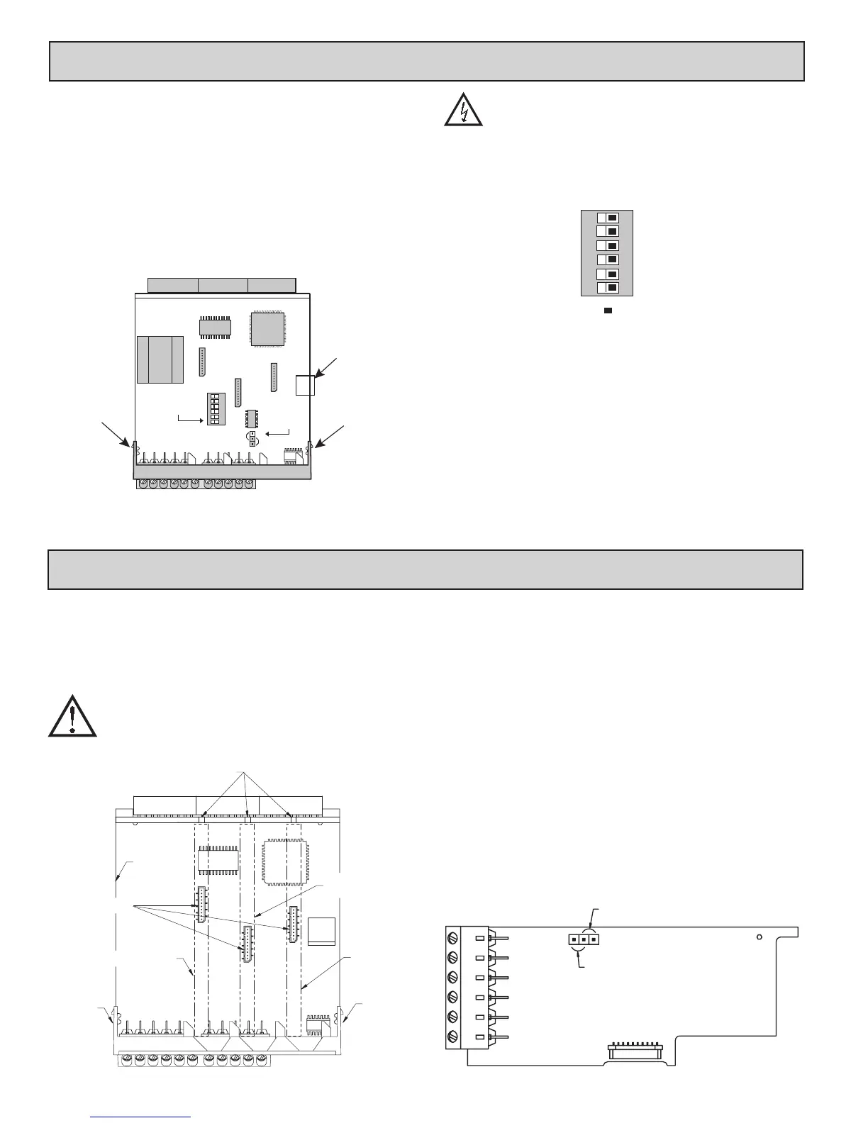
2.2 SETTING THE INPUT DIP SWITCHES
The meter has six DIP switches for Input A and Input B terminal set-up that
must be set before applying power. NOTE: The PAXR only uses switches 1-3.
SWITCHES 1 and 4
LOGIC: Input trigger levels V
IL
= 1.5 V max.; V
IH
= 3.75 V min.
MAG: 200 mV peak input (must also have SRC on). Not recommended with
counting applications.
SWITCHES 2 and 5
SRC.: Adds internal 3.9 KΩ pull-down resistor, 7.3 mA max. @ 28 VDC,
V
MAX
= 30 VDC.
SNK.: Adds internal 7.8 KΩ pull-up resistor to +12 VDC, I
MAX
= 1.9 mA.
SWITCHES 3 and 6
HI Frequency: Removes damping capacitor and allows max. frequency.
LO Frequency: Adds a damping capacitor for switch contact bounce. Also
limits input frequency to 50 Hz and input pulse widths to 10 msec.
Main
Circuit
Board
REAR TERMINALS
INPUT SET-UP
DIP SWITCHES
USER
INPUT
JUMPER
1
2
3
4
5
6
SRC
SNK
Finger
Tab
Finger
Tab
USB
Connector
To access the jumper and switches, remove the meter base from the meter
case by firmly squeezing and pulling back on the side rear finger tabs. This
should lower the latch below the case slot (which is located just in front of the
finger tabs). It is recommended to release the latch on one side, then start the
other side latch.
Warning: Exposed line voltage exists on the circuit boards. Remove
all power to the meter and load circuits before accessing inside of
the meter.
6
5
4
3
2
1
ON
Input B SRC.
Input B LO Freq.
Input B MAG.
Input A LO Freq.
Input A SRC.
Input A MAG.
SNK.
HI Freq.
Logic
HI Freq.
SNK.
Logic
Factory Setting

 Loading...