POWER WIRING
The power supplied to the meter shall employ a 15 Amp UL
approved circuit breaker for AC input and a 1 Amp, 250 V UL
approved fuse for DC input. It shall be easily accessible and
marked as a disconnecting device to the installed unit. This device
is not directly intended for connection to the mains without a
reliable means to reduce transient over-voltages to 1500 V.
1
2
AC/DC
AC/DC
1
2
AC/DC
AC/DC
+
-
1
2
AC/DC
AC/DC
+
-
OR
AC Power
DC Power
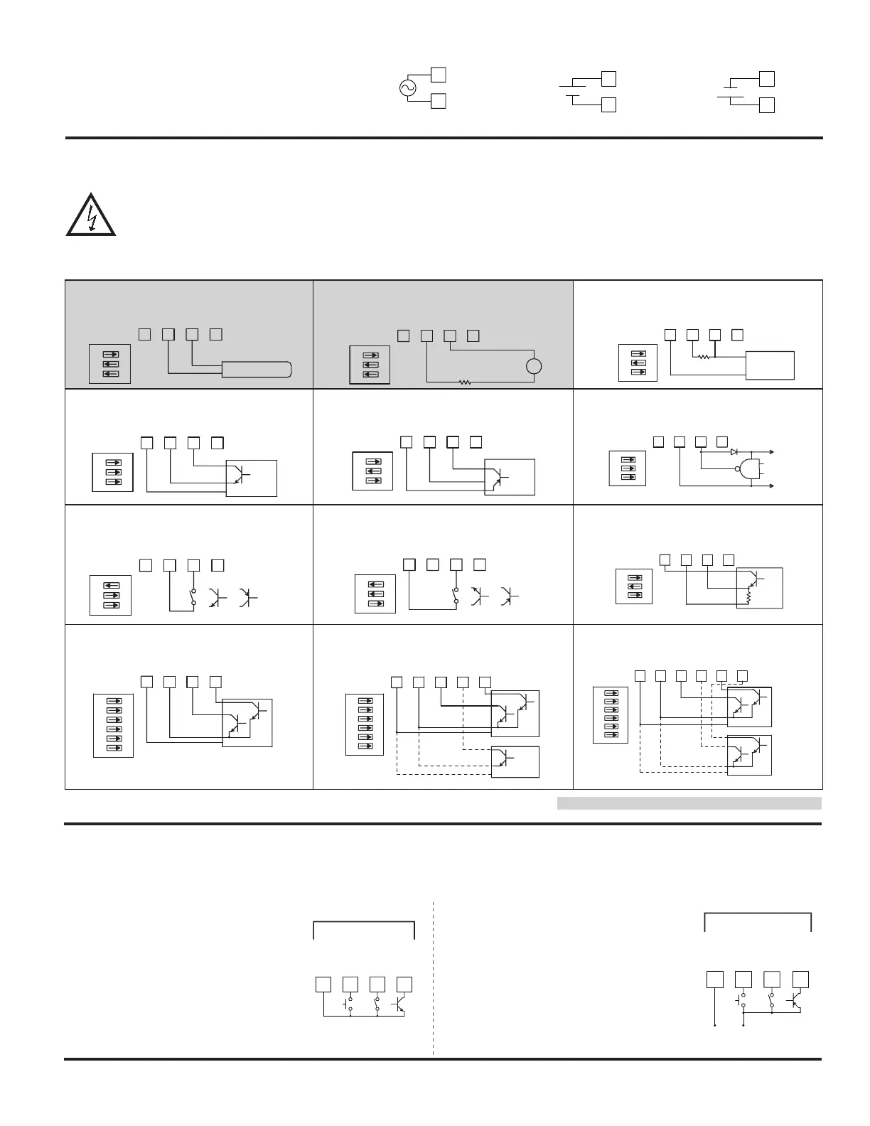
INPUT SIGNAL WIRING
CAUTION: Sensor input common is NOT isolated from user input common. In order to preserve the safety of the meter application, the sensor input
common must be suitably isolated from hazardous live earth referenced voltage; or input common must be at protective earth ground potential. If not,
hazardous voltage may be present at the User Inputs and User Input Common terminals. Appropriate considerations must then be given to the potential
of the user input common with respect to earth ground; and the common of the isolated plug-in cards with respect to input common.
345
MAGNETIC PICKUP
6
+18V
OUT
COMM
INPUT A
INPUT B
3
1
2
ON
63 4 5
to 2.5 mA MAX.
Resistor to limit current
AC
+18VOUT
COMM
INPUT A
INPUT B
3
2
1
ON
43 5 6
2.2KΩ
COMM
+18V
OUT
INPUT B
INPUT A
2
1
3
ON
NPN O.C.
3 4 5 6
COMM
+18V
OUT
INPUT A
INPUT B
1
2
3
ON
PNP O.C.
3 4 5 6
+18VOUT
COMM
INPUT A
INPUT B
2
1
3
ON
ON
4
2
3
1
3 5 6
+5V
COMM
DIODE
+18VOUT
COMM
INPUT B
INPUT A
3 4 5 6
INPUT A
INPUT B
COMM
+18V
OUT
2
1
3
ON
63 4 5
INPUT A
INPUT B
+18V
OUT
COMM
1
2
3
ON
3 4 5 6
INPUT A
INPUT B
+18V
OUT
COMM
2
1
3
ON
AC Inputs From Tach Generators, Etc.
Input A
Two Wire Proximity, Current Source
Input A
Magnetic Pickup
Input A
Current Sourcing Output
Input A
Interfacing With TTL
Input A
Current Sinking Output
Input A
Switch or Isolated Transistor; Current Sink
Input A
Switch or Isolated Transistor; Current Source
Input A
Emitter Follower; Current Source
Input A
63 4 5
NPN O.C.
+18VOUT
COMM
INPUT A
INPUT B
4
1
2
3
6
5
ON
3 4 5 6
NPN O.C.
Count A
8 9
NPN O.C.
Count B
+18VOUT
COMM
INPUT A
INPUT B
3
2
1
ON
4
5
6
USER 1
USER 2
Quad; Current Sink Output
Single
Counter A
Counter A &
Counter B
Dual Quad/Quad; Current Sink Output
If you are wiring Input B, connect signal to Terminal 6 instead of 5, and set DIP switches 4, 5, and 6 to the positions shown for 1, 2, and 3.
Shaded areas not recommended for counting applications.
63 4 5
NPN O.C.
NPN O.C.
8
Rate
Count
+18VOUT
COMM
USER 1
INPUT A
INPUT B
4
1
2
3
6
5
ON
Dual Quad/Count; Current Sink Output
Counter A
& Rate B
If using single Counter B, then wire signal to 6,
and Quad/Direction to 9. Set switches as shown.
USER INPUT WIRING
If User Input 1 and/or 2 are wired for quadrature or directional counting, an additional switching device should not be
connected to that User Input terminal. User Input terminal does not need to be wired in order to remain in inactive state.
Sourcing Logic (USrACt HI)
When the USrACt parameter is programmed to HI,
the user inputs of the meter are internally pulled
down to 0 V with 20 K
Ω resistance. The input
is active when a voltage greater than 2.2 VDC
is applied.
USER INPUTS
USER 3
USER 2
USER 1
COMM.
7 8 9 10
Sinking Logic (USrACt LO)
When the USrACt parameter is programmed to
LO, the user inputs of the meter are internally
pulled up to +3.3 V with 20 K
Ω resistance. The
input is active when it is pulled low (<1.1 V).
+
(30V max.)
SUPPLY
V
USER 3
USER 2
USER 1
COMM.
87
-
109
USER INPUTS
Buy: www.ValinOnline.com | Phone 844-385-3099 | Email: CustomerService@valin.com

 Loading...


