19
ALARM HYSTERESIS
The Hysteresis Value is either added to or subtracted from the alarm value,
depending on the alarm action selected. The same value applies to both alarms.
See the Alarm Action Figures at the beginning of this section for a visual
explanation of how alarm actions are affected by the hysteresis.
to
CHANGE COLOR
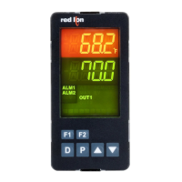
Select alarm(s) to change Input Display color intensity when appropriate
alarm(s) are triggered.
AL-3
AL-2AL-1ANYOFF
Cl
ALARM 3 STANDBY
Standby prevents nuisance (typically low level) alarms after a power up.
After powering up the controller, the process must leave the alarm region (enter
normal non-alarm area of operation). After this has occurred, the standby is
disabled and the alarm responds normally until the next controller power up.
ALARM 3 VALUE
The alarm values are entered as process units or degrees. They can also be
entered in the Parameter or Hidden Loops. When the alarm is configured as
deviation or band acting, the associated output tracks the Setpoint as it is
changed. The value entered is the offset or difference from the Setpoint.
ALARM 3 RESET MODE
In Automatic mode, an energized alarm turns off automatically after the
Temperature/Process value leaves the alarm region. In Latched mode, an
energized alarm requires an 1 / 2 key or user input alarm reset to turn off. After
an alarm reset, the alarm remains reset off until the trigger point is crossed again.
Automatic
Latched
Standby on
Standby off
to
19
7.5 mOdule 7 - serial COmmuniCaTiOns parameTers (C)
tYPE dAtAbAUd
COMUNICATIONS
BAUD
DATA
7-SC
CNFP
PArb
PARITY
Addr
UNIT
P
P
PARAMETER MENU
38K4
8
DATA BIT
NO
PARITY BIT
2400 600
400 1K2
3K4
7
NO EvEN Odd
BAUD RATE
Set the baud rate to match that of other serial communications equipment.
Normally, the baud rate is set to the highest value that all of the serial
communications equipment is capable of transmitting.
Select either 7 or 8 bit data word lengths. Set the word length to match that
of other serial communication equipment. If rtU is selected as the communication
type, dAtA defaults to 8.
Set the parity bit to match that of the other serial communications equipment
used.
247
UNIT ADDRESS
1 to 247
Select a Unit Address that does not match an address number of any other
device on the serial link.
COMMUNICATIONS TYPE
ModBus RTU
C ModBus ASCII
Select the desired communications protocol.
3
b3
3
3
INPUT FAIL ALARM 3 ACTION
I3
Select the Alarm action in the event of a detected input failure (open TC/RTD
or shorted RTD).
Shaded parameters are programming/model dependent.
 Loading...

