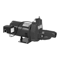
Nozzle
Venturi
Part No.
Throat
Part No.
Fig. 1
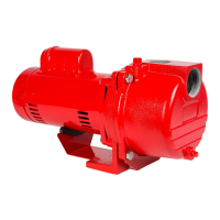
APPLICATION
This pump is designed to be used with shallow wells down to 25 ft
(7.6 m)* and deep wells down to 90 ft (27.4 m)*. The pump includes an
injector kit, which consists of a cast iron injector assembly that has a
nozzle and venturi threaded into it (see Fig. 1). This injector assembly is
set up for shallow well use. Additional venturis are included for deep well
applications. Some models also include a deep well nozzle. The venturi and
nozzle are designed specifically for certain depths to optimize performance.
The injector assembly should always be replaced at the same time the
pump is replaced. Follow the Convertible Jet Pump Injector Kit instructions
to ensure the proper venturi and nozzle are set up in the injector assembly.
The Detailed Installation Instructions section provides further information
for attaching the injector assembly. In deep well installations, friction
losses in the suction pipe must be taken into consideration (refer to
Table 1, Friction Loss Chart).
*Less at high altitudes.
NOTE: This pump is not tested for use in swimming pools.
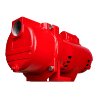
VOLTAGE WIRING INSTRUCTIONS
DISCONNECT UNIT FROM POWER SOURCE BEFORE PROCEEDING.
ENSURE THE PUMP’S VOLTAGE MATCHES THE VOLTAGE OF
YOUR POWER SOURCE.
NOTE: DO NOT MOVE WHITE LEAD WIRES ON L1 & L2
In Fig. 2, the motor's switch is shown before the black voltage change
device is pressed down onto the voltage terminals.
Fig. 2
Terminal Board
Voltage Change Device
In Fig. 3, the motor's switch is set for 115 V. The black voltage change device
is pressed down onto both terminals with the white arrow point on the
voltage change device pointing directly to the 115 V arrow point on the
terminal board.
Fig. 3 (Set to 115 V)
In Fig. 4, the motor's switch is set for 230 V. The black voltage change device
is pressed down onto only one terminal with the white arrow point on the
voltage change device pointing directly to the 230 V arrow point on the
terminal board.
Fig. 4 (Set to 230 V)
4
 Loading...