19
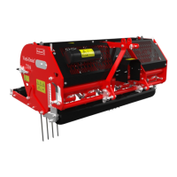
16.0 OPTIONS, WHEEL KIT.
The part number for a full transport kit for the 7521 is 9500110. This kit will be separately delivered and can be
mounted to a standard 3-point linkage machine. Generally speaking, a machine with wheel kit will reduce the
minimum horsepower required by 10 HP. It also can be taken off quickly, so the machine can be used either
way
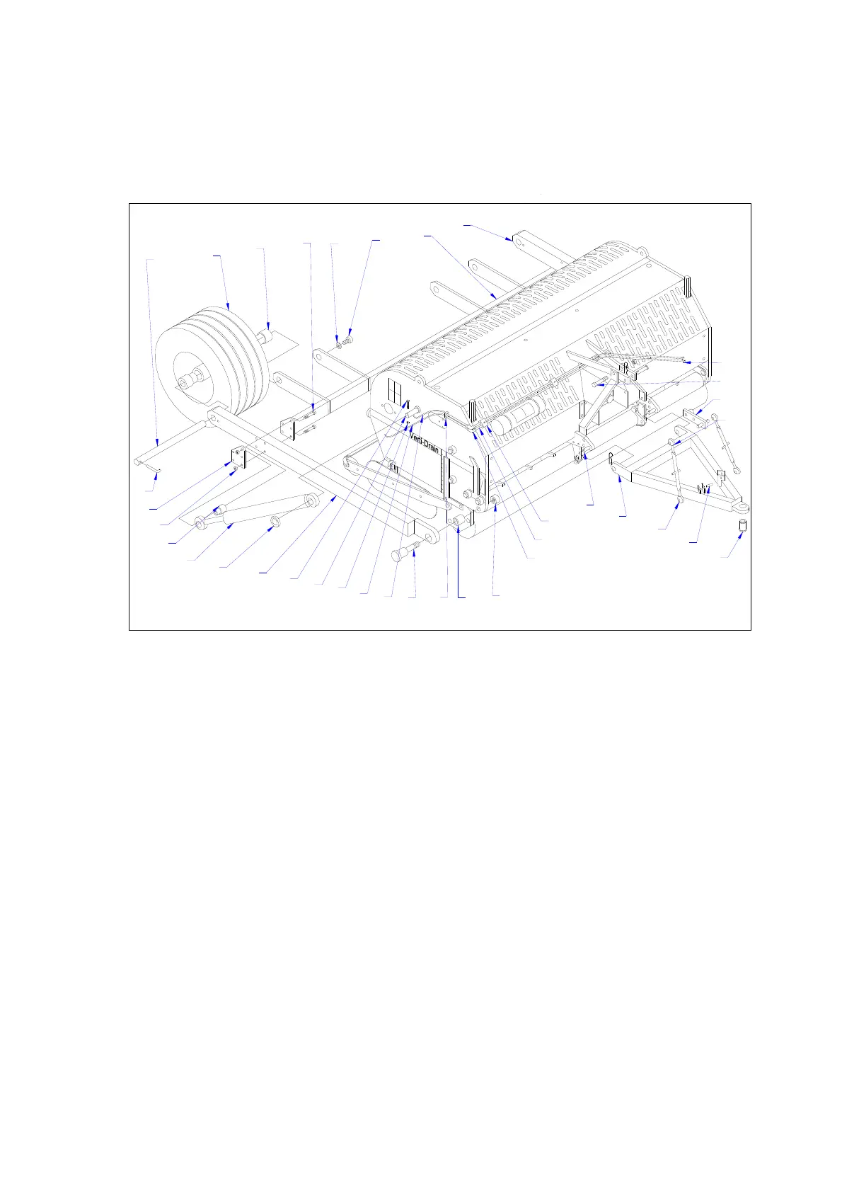
16.0.1 MOUNTING THE WHEELKIT TO THE MACHINE.
Work as follows, see fig.10.:
1. Unpack all parts and lay them down.
2. Put machine horizontal on a hard floor with locked rear roller and in deepest working position.
3. Assemble pins Q in main frame each side and tighten nut inside.
4. Fix the arms O with pin U and distance washer W tight to machine with nut X..
5. Assemble the hydraulic cylinder M to pin Q and secure it with bolt/nut P/R. Use distance washer N.
6. Mount the rear beam B between both legs O using the 4 main bolt/nuts E/K and plate J. Before
tightening, assemble the hydraulic cylinder rod end with distance bush L with a similar bolt and nut. Do
not tighten the bolts/nuts yet.
7. Mount the rear wheels G with main shaft H (first put bush F at each bearing of the wheel) and lock
pin I to the leg O and rear beam B and secure it with bolt C and (spring) washer D.
8. Tighten all bolts/nuts E/K.
9.Reposition the standard bottom 3-point pins on the Verti-Drain to the front hole, both facing to the
right (standing behind machine).
10. Fix the draw bar AB to both repositioned 3-point pins and lock with linch pin.
11. Assemble the top link support AH at the standard bolt AG and lock it with the standard toplink pin.
Assemble it in the position drawn.
AC
P
I
J
K
L
M
N
O
Q
R
S
T
U
V
W
X
Y
Z
V
AA
AB
F
G
H
A
B
C
D
E
AF
AD
AE
AH
AG
AI
Fig.10.