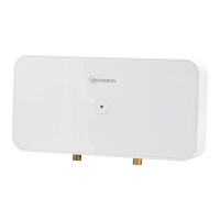
Wiring Lug Removal
• Follow steps A-D in Diagram 3 above to remove plastic lug.
• Feed cable through rubber gland in metalwork.
Fixing to the wall
• Undo the retaining nuts and take the front cover
off the unit. Hold the backplate in position against
the wall whilst you mark the four fixing holes.
• Drill the holes and fix the unit to the wall using
the screws supplied.
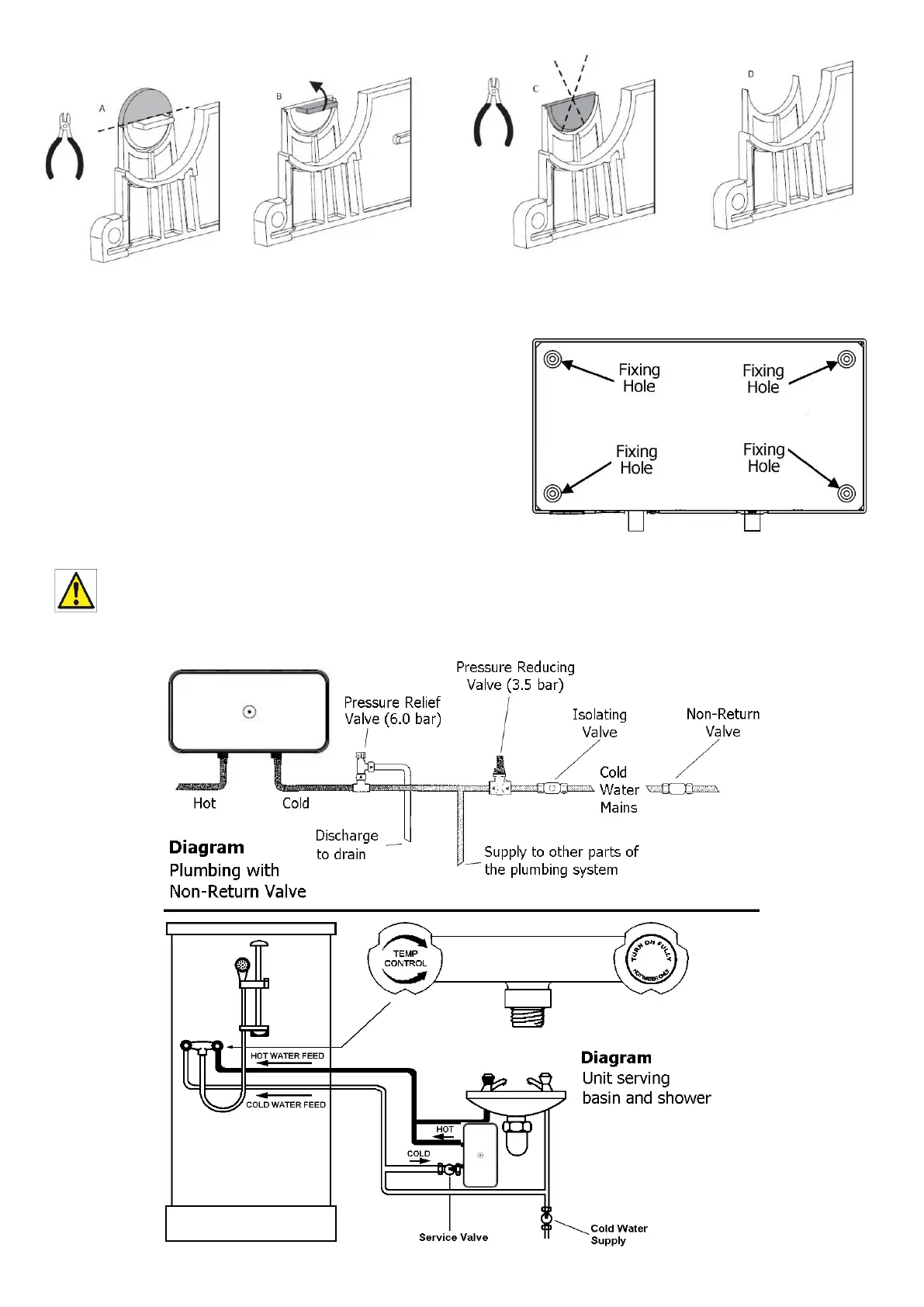
IF A NON-RETURN VALVE IS FITTED AND/OR THE INLET FEED TO THE UNIT IS
GREATER THAN 6BAR, THEN THE INSTALLATION MUST ALSO INCLUDE A 3.5 BAR
PRESSURE REDUCING VALVE AND A 6 BAR PRESSURE RELIEF (EXPANSION)
VALVE AS SHOWN IN DIAGRAM 5a.
 Loading...