Installation: As figure 4, put light tube (1) on the hold(2), and insert the tube power input plug into
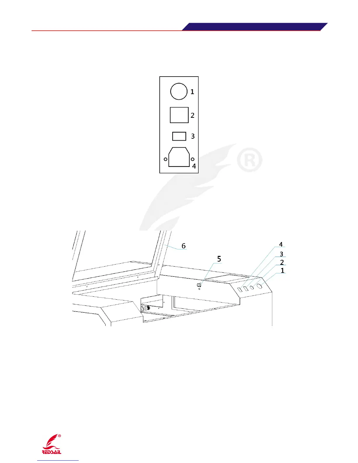
3.5 Instructions of the power input / output of equipment
(Figure 5)
1
:
Main power switch : the total power of control equipment 2.Lamp switch: Control lighting inside
the device 3
:
Laser Switch: Control laser beam switch. 4
:
Input voltage: 220V
3.6 Auxiliary Control Area Instruction
(Figure 6)
1·Emergency stop switch: Control the power on/off for the main part, such as switch power supply,
laser power supply and so on.
2·Cover protection switch: control device to open and close the cover , the device processing and
pause function. The machine will work eigher the cover is opened or closed when the key is turned to
the right. When the key is opened and the cover is closed, the machine will begin to work by pressing
“OK” button on the control panel, the machine will stop working when opening the cover.
3·Red Dot indicator lamp(Optional): When open this switch, the indicator will be on(installed on
laser head), for fix origin point and fix the position of laser beam.
4·Spare