8
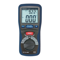
6. During testing, the upper right of the LCD display will show the test
voltage applied while a high voltage symbol will ash every 2 to 3
seconds. The main display will indicate the resistance.
7. When the reading is stable, note the measured value.
8. When testing is complete, release the TEST button and make sure to
keep the test leads connected to the equipment under test
during discharge.
Note: The charge stored in the insulation meter will be automatically
discharged when the TEST button is released.
Insulation Resistance Measurement Notes:
1. The maximum measurement range is 2000MΩ. When insulation
resistance exceeds this value, the LCD display will indicate "1",
meaning that the resistance is very high and the insulation being
tested is good.
2. Make sure that the circuit being tested does not include components
which will be damaged by the 1000V applied. Many normal
components of an installation are likely to be damaged if tested at
1000V. Examples are power factor correction capacitors, low voltage
mineral insulated cables, electronic light dimmers, electronic ballasts
and starters for uorescent lamps etc.
Lock Power Function
The R5600 features a lock power function to allow hands free operation
during insulation resistance testing. To enable, follow the steps below:
1. Once the meter is ready for testing, simultaneously press the TEST
and LOCK buttons to enable hands free operation.
2. While in this mode, the
LOCK icon will appear on the LCD display
and the meter will emit a beeping sound every 2 seconds conrming
it is in lock mode.
3. To exit the lock power function and end testing, press the
LOCK button.
Note: The charge stored in the insulation meter will be automatically
discharged.
continued...
REED Instruments
1-877-849-2127 | info@reedinstruments.com | www.reedinstruments.com