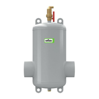
3.4 Installation and assembly
3.5 Notes
The following items must be considered when assembling and installing the equipment:
• The flow direction is not pre-determined.
• Ensure a vertical and stress-free installation.
- Any stresses that may occur in some cases must be countered by appropriate constructive actions. Stresses may be caused by
temperature effects, for example.
• Ensure sufficient bearing capability of the installation site.
- This applies to filling the separator with water in particular.
• The equipment is not a load-bearing construction element.
- By default, the calculation of the vessels does not take lateral acceleration forces into account. Avoid alternating stresses such as
pressure shocks, abrupt pressure changes, or strong
vibrations.
• Use only approved transport and lifting gear.
- The eyes provided on the device are intended solely as
installation aids.
• The angle (1) of the lifting tackles must be maximum 60°.
3.6 Space requirements
A: Minimum free space above the top part of the ventilation


 To Next Page