STR 0PA 15
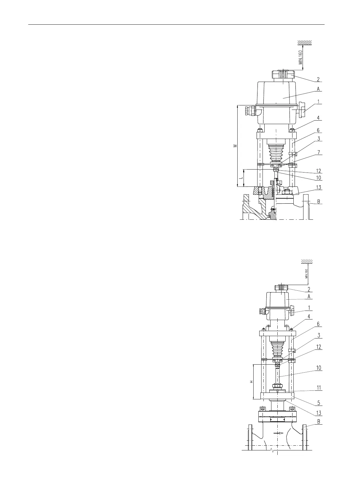
Mechanical connection for pillar version - Fig. 3
Connection procedure:
• Check the labels, whether the travel of electric actuator and
travel of armature are corresponding.
• The valve (B) is put to the position „closed“ and the actuator (A) to
a half-position.
• Loosen the nuts (4) on the pillars (6).
• Screw the pillars (6) with the cross system into the valve flange
(13).
• Tighten the pillars (6) nuts.
• Unscrew the coupling (3) screws (7) to dismantle the coupling into
parts.
• Screw the coupling (3) nut onto the valve shaft (10) to reach the
connecting size L in accordance with the table and the actuator
nameplate.
• Unscrew the coupling (3) nut by one revolution and lock it by a nut
(12).
• Use the hand wheel (2) to put the actuator output shaft next to the
valve (10), and screw the coupling parts together.
A ........... electric actuator B ................ valve
1 ........... disengagement button 10 ............... valve shaft
2 ........... hand wheel 12 ............... locking nut
3 ........... coupling nut 13 ............... valve flange
4 ........... pillar nut
6 ........... pillar
7 ........... coupling screw
Mechanic connection with the flange - (Fig. 4)
Connecting procedure:
• Check the labels, whether the travel of electric actuator and travel
of armature are corresponding.
• Set the armature (B) into position „closed“ and set electric actuator
(A) into half-position.
• Put electric actuator (A) on the armature (B).
• Unscrew the clutch bolts (3) and disassembly parts of the clutch.
• Screw the nut of clutch (3) on output shaft of armature (10) in a way,
that the flange of electric actuator (5) will fit to the flange of armature
(13).
• Connect the flanges by tightening of central nut (11).
• Check connecting dimension "H" between the clutch and the flange
(13) in the position of contact with pillars according to dimensional
drawing and a type number on the plate of electric actuator.
• Release the clutch nut (3) by one turn counter clockwise and secure it
by nut (12), thereby reaching pre-stress securing proper seating of
armature.
• By hand wheel (2) approach output shaft of electric actuator to the
shaft of armature (10) and fasten parts of the clutch by bolts.
A ...........electric actuator
1 ...........disengagement button
2 ...........hand wheel
3 ...........coupling nut
4 ...........pillar nut
5 ...........actuator flange
6............pillar
B ........... valve
10.......... valve
shaft
11... connecting nut
12 ............locking
nut
13 ............valve
flange
Fig. 3
Fig.4