STR 0PA 27
control knob is brought to the motor drive operation position, disconnect the supply voltage for about 3
seconds and reconnect it.
If some EA element would fail it can be replaced with a new one. The producer’s service centre only
is allowed for such replacement.
If your EA would fail, proceed please according to the instructions for the under guarantee and
after-guarantee service.
For repairing eventually the electronics use the fuse – see Fig.1a (F3) for example SHURTER MSF
250, or sub miniature SIBA 164050 xxx (see chapter 1.9.2), which is located on source board.
Note:
If the EA requires dismantling follow the chapter "Dismantling".
Taking the EA to pieces for repair purposes is allowed only by professionally qualified persons
trained in the production plant or by a contracted service centre!
5. Accessories and spare parts
5.1 Accessories
The EA is delivered with the service handle and communication cable DB-9F/RJ45.
5.2 Spare part list
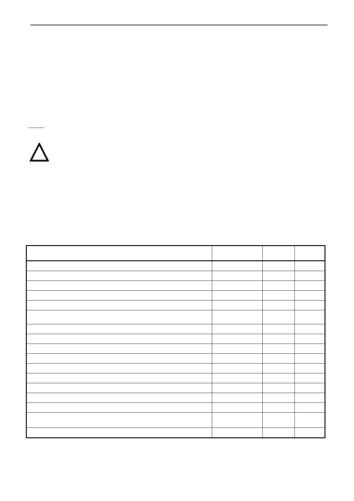
Table 4 Spare part Order Nr. Position
Figure
Electric motor; 2,75 W; 230/220 V AC 63 592 382
1 1
Electric motor; 2,75 W; 24 V AC 63 592 437
1 1
Control unit of the electronics DMS3 J1 (0/4/12 up to 20 mA, resp.4
up to 12 mA)
64 051 075
2
1
Control unit of the electronics DMS3 J3 (0/2 - 10 V) 64 051 061 2 1
Control unit of the electronics DMS3 J2 (without input and output) 64 051 060 2 1
DMS3 Z1 230 - source board of electronic for 230/220 V AC 64 051 076 3 1
DMS3 Z4 24A source board of electronic for 24 V AC 64 051 077 3 1
DMS3 Z2 115 source board of electronic for 115 V AC 64 051 062 3 1
Position scanning unit DMS3 SP 64 051 079 4 1
CHERRY DB 3G B1RB (the lever with roller is removed and
outlets shortened)
64 051 198 5 1
!