SP 1, SP 2, SP 2.3, SP 2.4 31
SPR1, SPR 2, SPR 2.3, SPR 2.4
Legend:
Z1a .................wiring diagram of 1-phase motor
Z5a .................wiring diagram of single resistant transmitter
Z6a .................wiring diagram of double resistant transmitter
Z10a ...............wiring diagram of resistive with current converter or captive transmitter - 2-wire without supply
Z11a ...............wiring diagram of position switches for 1-phase electric motor
Z12a ...............wiring diagram of switches for 3-phase electric motor
Z21a ...............wiring diagram of additional position switches connection for SP(R)
Z41a ...............wiring diagram of space heater and space heater’s thermal switch connection for SP(R)
Z78a................wiring diagram of 3-phase electric motor
Z90c................wiring diagram of 3-phase electric motor with electric local control
Z232f...............wiring diagram of electric local for SPR – voltage 230 V AC, 24 V AC
Z232g..............wiring diagram of electric local for SPR – voltage 24 V DC
Z240a .............wiring diagram of SP(R) with controller with resistant feedback for 1-phase electric motor
Z241a .............wiring diagram SP(R) with controller with current feedback for 1-phase electric motor
Z250a..............wiring diagram SP(R) with controller with current feedback for 3-phase electric motor
Z251a..............wiring diagram of SP(R) with controller with resistant feedback for 3-phase electric motor
Z257a .............wiring diagram of resistive transmitter with current converter -3-wire version without power
supply
Z260a, Z260f ...wiring diagram of resistive transmitter with current converter -3-wire version with power supply
Z269a .............wiring diagram of resistive transmitter with current converter or capacitive transmitter -2-wire
version with power supply
Z269f ..............wiring diagram of resistive transmitter with current converter or capacitive transmitter -2-wire
version with power supply – 24 V DC
Z270i, Z270k....wiring diagram of 1-phase electric motor with electric local control
Z288a..............wiring diagram of additional position switches for SP(R) for 3-phase electric motor
Z303................wiring diagram of 3-phase electric motor with reverse contactors
Z304a..............wiring diagram of 3-phase electric motor with reverse contactors and electric local control
Z341................wiring diagram of double torque switch
Z378 ...............wiring diagram of resistive with current converter or capacitive transmitter 2 and 3 - wire with
supply
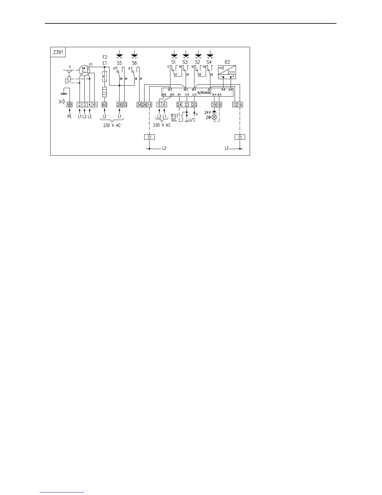
Z391................wiring diagram of 3-phase electric motor with controller and with current feedback, with power
supply 3x500 V
Z503 ...............connection of EA SP 1 with electric motor 24 V DC
Z503a..............connection of EA SP 2, SP 2.3, SP 2.4 with electric motor 24 V DC
Z505a..............connection of EA SP 2, SP 2.3, SP 2.4 with electric motor 24 V DC and with local control
Z505b .............connection of EA SP 1 with electric motor 24 V DC and with local control
Z507................connection of EA SP1 with electric motor 24 V AC
Z507a..............connection of EA SP 2, SP 2.3, SP 2.4 with electric motor 24 V AC
Z509a..............connection of EA SP 2, SP 2.3, SP 2.4 with electric motor 24 V AC and with local control
Z509b..............connection of EA SP 1 with electric motor 24 V AC and with local control
Z519a..............connection of SPR 1 with controller and resistant feedback for electric motor 24 V DC
Z519b..............connection of SPR 2 – SPR 2.4 with controller and resistant feedback for electric motor 24 V DC
Z520a..............connection of SPR 1 with controller and current feedback for electric motor 24 V DC
Z520b..............connection of SPR 2 – SPR 2.4 with controller and current feedback for electric motor 24 V DC
ERROR
MESSAGE