16 ST 0, STR 0
3.1 Gear unit adjustment
The switching thrust values both for the direction „opening“ (the thrust switch S1) and for the
direction „closing“ (the thrust switch S2) are in the production plant adjusted to the rated thrust with
tolerance ±10%. The numeric values are given in the corresponding specification table. Adjustment
and resetting of the gear unit to other thrust values are not possible without having a special test
device to measure thrust values.
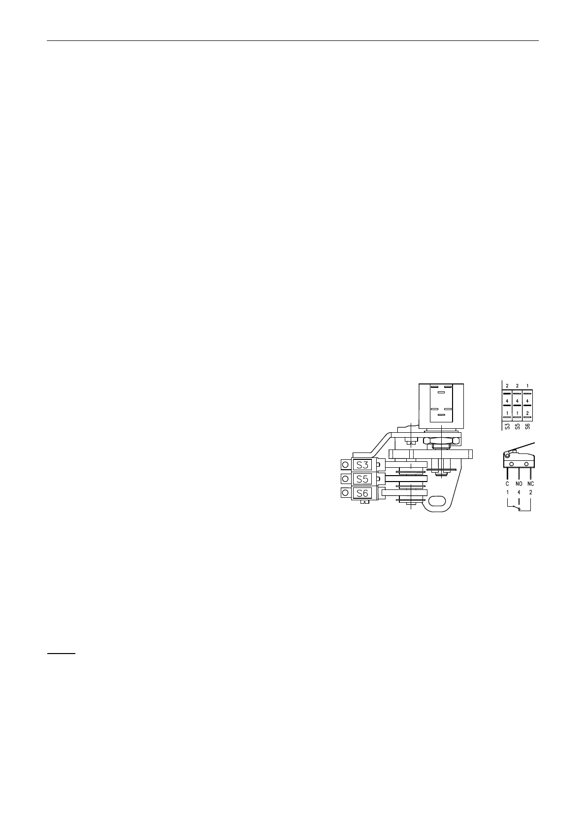
3.2 Position unit adjustment (Fig. 6)
The position switches are to be adjusted with setting the cams switching them. Turning the cam
is performed with a screwdriver put into the cam groove.
Adjustment of the S3 limit switch
In case of the one-thrust wiring of the actuator the electric motor is during the actuator motion in
the direction „opening“ fed through the S3 position switch. If it is out of tune follow these steps:
• Put the actuator and the controlled device to the required position „open“.
• Turn the cam switching the switch S3 clockwisely until the switch S3 switches.
Adjustment of the additional position switches
The switches are in the plant adjusted to switching ca. 1mm before the correspondent limit
position of the actuator.
While adjusting of the switches S5 and S6 follow these steps:
• Put the actuator to the position where the switch S5
should indicate the position „open“.
• Turn the cam switching the switch S5 clockwisely until
the switch S3 (14) switches.
• Put the actuator to the position where the switch S6
should indicate the position „closed“.
• Turn the cam switching the switch S6 counter
clockwisely until the switch S6 switches.
S3 – position switch "open"
S5 – additional position switch "open"
S6 – additional position switch "closed"
Fig.6
3.3 Adjustment of resistant transmitter
The resistant transmitter is in the EA ST used to function as a remote position indicator; in the
EA STR to function as a feedback in the position controller and if needed also in the position of a
remote resistant position indicator.
The potentiometer is not needed to be adjusted, it is able to adjust itself with putting the actuator
to the both limit positions in accordance with the stroke specified on the nameplate.
Notes:
1. If the actuator was adjusted to another stroke the transmitter resistance in the limit positions should not
correspond with the technical parameters given in the chapter 1.7.
2. In case that the EA is not used in the whole stroke range given on the nameplate, the resistance in the limit
position "open" is proportionally reduced.
3. In the EA STR 2000Ω resistant transmitters are used. In the other cases if the resistant branch is lead to the
terminal board the resistance of the transmitters is according to the customer's specification.