ST 0, STR 0 17
3.4 Adjustment of the Electronic Position Transmitter (EPV) - the Resistive
Transmitter (Potentiometer) with the Converter PTK 1
The position transmitter with the converter is in the plant adjusted to have the output current
signal on the terminals 81-82 as follows:
• in the position ”open“ .................... 20 mA
• in the position ”closed“ .................. 4 mA
If the transmitter requires a new adjustment follow these
steps:
Adjustment of the EPV – the 2-wire version:
• Put the actuator to the position ”closed“ and switch the
power supply off.
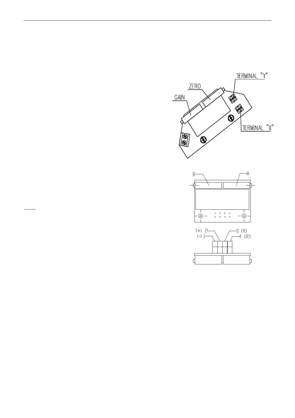
• Adjust the resistive transmitter according to the
previous chapter. The resistance is to be metered on
the terminals X-Y (Fig. 7, 7a). The used transmitter
resistance is 100 Ω.
• Switch the converter′s power supply on.
• Turn the adjusting trimmer ZERO resp. A to adjust the
output current signal rate measured on the terminals 81-82 to 4mA.
• Set the actuator to the position ”open“.
• Turn the adjusting trimmer GAIN resp. B to adjust the output
current signal rate measured on the terminals 81-82 to 20mA.
• Check the output signal of the converter in the both limit
positions, and repeat the procedure if needed.
Note:
The output signal of 4-20mA can be adjusted at the range from 75 up to
100% of the rated stroke stated on the actuator′s nameplate. At values
less than 75% the value 20mA is reduced proportionally.
Adjustment of the EPV in Electric Actuators STR with controllers
• Disconnect the circuit with removing a jumper on the terminals 81 and 82.
• Disconnect the control signal from the terminals 86/87 and 88.
• Set the actuator to the direction ”OPENING” or “CLOSING” with the handwheel, or with
connecting power to the terminals 1 and 20 for the direction “OPENING” or 1 and 24 for the
direction “CLOSING”.
• Set the actuator to the position “CLOSING“ and switch the converter off on the terminals 1 a 61.
• Adjust the resistive transmitter according to the previous chapter. The resistance is to be metered
on the terminals X-Y (Fig. 7).
• Connect power supply to the terminals 1 and 61.
• Turn the adjusting trimmer ZERO (Fig. 7) to adjust the output current signal rate measured on the
terminals 81-82 to 4mA.
• Set the actuator to the position “open”.
• Turn the adjusting trimmer GAIN (Fig. 7) to adjust the output current signal rate measured on the
terminals 81-82 to 20mA.
• Check the output signal of the converter in the both limit positions, and repeat the procedure if
needed.
Fig. 7a
Fig.7