12 ST 0, STR 0
2.1 Installation
EA is by the producer adjusted to parameters according to the nameplate, with connecting
dimensions according to the corresponding dimensional drawing and put it to a mid-position.
Before installation put the handle on.
2.1.1 Mechanical connection
The actuators can be installed and operated in any position. While installing leave enough space
for dismantling of the upper cover to allow adjusting of the control parts.
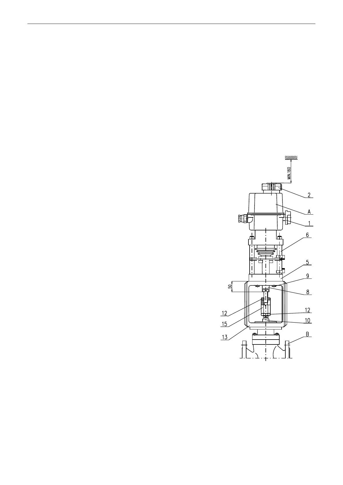
Mechanical connection with connection dimensions according to DIN Standards (Fig. 2)
Connection procedure:
• Set the actuator (A) and the valve (B) to the position „closed“.
• Put the actuator (A) onto the valve (B).
• Screw the actuator shaft (8) into the valve coupling (15) until
the actuator flange seats on the valve body (13).
• Tighten the screws (9) to connect the actuator flange (5) with
the valve body (13).
• Check connection dimensions in accordance with Fig. 1.
• Turn the valve output shaft by one revolution and lock it with
the nut (12).
A .......... electric actuator
1 .......... disengagement button
2 .......... hand wheel
5 .......... actuator flange
6 .......... pillar
8 .......... actuator output shaft
9 .......... screw
B .......... valve
10 ........ valve output shaft
12 ........ locking nut
13 ........ valve body
15 ........ valve coupling
Fig.2