ST 0, STR 0 13
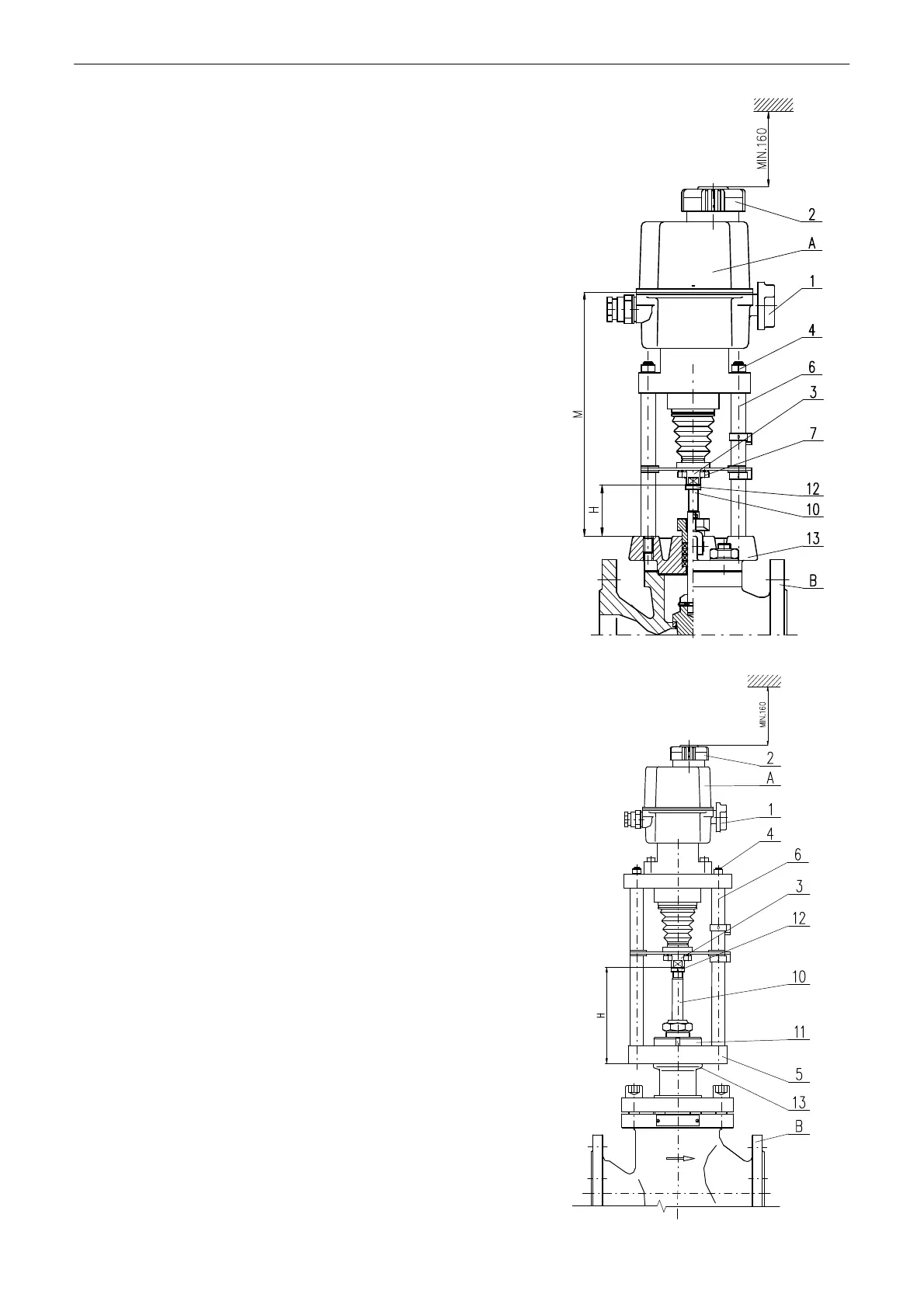
Mechanical connection for pillar version - Fig. 3
Connection procedure:
• The valve (B) is put to the position „closed“ and the
actuator (A) to a mid-position.
• Loosen the nuts (4) on the pillars (6).
• Screw the pillars (6) with the cross system into the valve
flange (13).
• Tighten the pillars (6) nuts.
• Unscrew the coupling (3) screws (7) to dismantle the
coupling into parts.
• Screw the coupling (3) nut onto the valve shaft (10) to
reach the connecting size H in accordance with the table
and the actuator nameplate.
• Unscrew the coupling (3) nut by one revolution and lock it
by a nut (12).
• Use the hand wheel (2) to put the actuator output shaft
next to the valve (10), and screw the coupling parts
together.
A ............ electric actuator
1 ............. disengagement button
2 ............. hand wheel
3 ............. coupling nut
4 ............. pillar nut
6 ............. pillar
7 ............. coupling screw
B ............ valve
10 ........... valve shaft
12 ........... locking nut
13 ........... valve flange
Mechanical connection for versions with flange (Fig. 4)
Connection procedure:
• Set the actuator (A) and the valve (B) to the position
„closed“.
• Place the actuator (A) onto the valve (B).
• Tighten the central nut (11) to connect flanges (13) and
(5).
• Unscrew the coupling (3) screws to dismantle the coupling
into parts.
• Screw the coupling (3) nut onto the valve shaft (10) to
reach the connecting size H in accordance with the table
and the actuator nameplate.
• Unscrew the coupling (3) nut by one revolution and lock it
by a nut (12) to create the prestress onto the valve seat.
• Use the hand wheel (2) to put the actuator output shaft
near the valve (10), and screw the coupling parts together.
A ............ electric actuator
1 ............. disengagement button
2 ............. hand wheel
3 ............. coupling nut
4 ............. pillar nut
5 ............. actuator flange
6 ............. pillar
B ............ valve
10 ........... valve shaft
11 ........... central nut
12 ........... locking nut
13 ........... valve flange
Fig. 3
Fig.4