14 ST 0, STR 0
Mechanical connection for versions with flange TGL
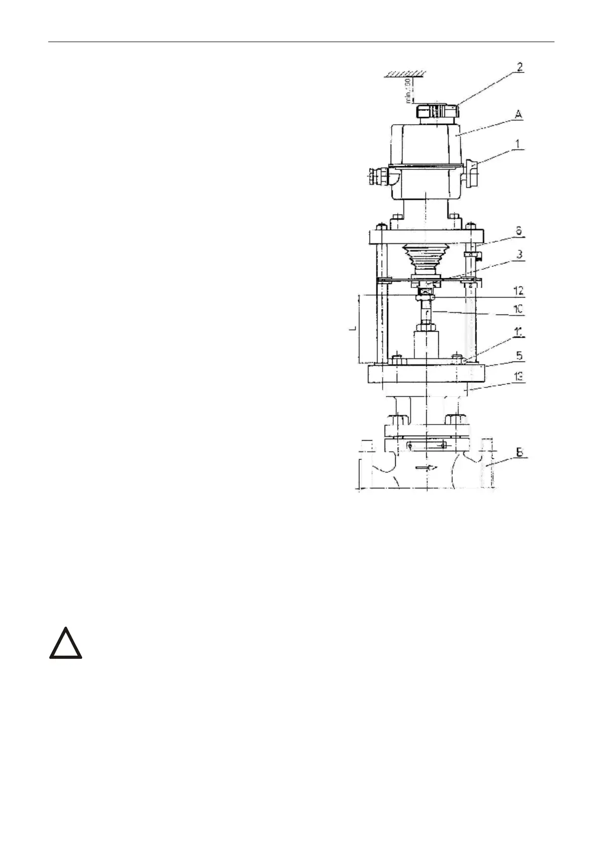
(Fig. 5)
Connection procedure:
• Set the actuator (A) and the valve (B) to the position
„closed“.
• Place the actuator (A) onto the valve (B).
• Tighten the clamp nuts (11) to connect flanges (13)
and (5).
• Unscrew the coupling (3) screws to dismantle the
coupling into parts.
• Screw the coupling (3) nut onto the valve shaft (10) to
reach the connecting size H in accordance with the
table and the actuator nameplate.
• Unscrew the coupling (3) nut by one revolution and
lock it by a nut (12) to create the prestress onto the
valve seat.
• Use the hand wheel (2) to put the actuator output
shaft next to the valve (10), and screw the coupling
parts together.
A .......... electric actuator
1 .......... disengagement button
2 .......... hand wheel
3 .......... coupling nut
5 .......... actuator flange
6 .......... pillar
B .......... valve
10 ........ valve shaft
11 ........ connecting nut
12 ........ locking nut
13 ........ valve flange
2.1.2 Electric connection and checking of function
1. Follow instructions in the part "Requirements for professional qualification"!
2. While laying electrical line abide by the instructions for heavy current installations.
3. Cables to terminal boards or connectors lead through cable glands. The cable jacket diameters must
conform to the extent specified in Chapter 1.8.3!
4. Before initiation ES into operation internal and external protection terminals are needed to be connected.
5. Feeding cables are to be fixed to the solid construction at most 150 mm from the cable glands.
6. It is recommended to use screened cables to connect remote transmitters.
7. To prevent moisture from entering the actuator around the connecting cables, the cables must be sealed with
silicone material at the point of penetration through device shell.
!
Fig. 5