ST 0, STR 0 19
3.5.1 Setting of controller
The controller's microprocessor unit is in the production plant programmed to parameters given
in Table 2 (Note 2).
Setting of the controller is performed using buttons and LED diodes.
Adjust the position and thrust switches and the position transmitter before adjustment of the
controller.
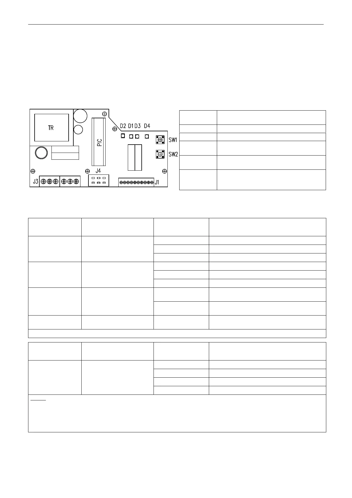
Laying of adjusters and signalling elements on the board of the REGADA controller is shown on Fig. 9:
Fig. 9
Table 2:
D3 (yellow) diode
number of blinking
Adjust menu
D4 (red) diode
number of blinking
Adjusted parameter
1 blink 0-20mA
2 blinks
4-20 mA (*) (**) 1 blink control signal
3 blinks 0-10V DC
1 blink EA opens receiving signal SYS
2 blinks EA closes receiving signal SYS
2 blinks
response for signal
SYS-TEST
3 blinks
EA stops receiving signal SYS (*)
1 blink
EA CLOSING at increasing of control
signal
3 blinks
mirroring
(ascending/descending
characteristics)
2 blinks
EA OPENING at increasing of control
signal (*)
4 blinks
insensitiveness of
controller
1 to 10 blinks
insensitiveness of controller of 1-10%
(3% set by the producer) (*)
CONTINUE >>>
D3 (yellow) diode
number of blinking
Adjust menu
D4 (red) diode
number of blinking
Adjusted parameter
1 blink narrow thrust
2 blinks
narrow position (*)
3 blinks wide thrust
5 blinks way of regulation
4 blinks wide position
Notes:
1. The controller at autocalibration automatically sets the feedback type - resistant/current
2. (*) Parameters set in the production plant, if customer has not stated else.
3. (**) Input signal 4 mA - position "closed"
20 mA - position "open"
Standard setting of controller (programmed RESET of controller) - in case of any problems with
setting of the parameters it is possible with pressing both SW1 and SW2 at the same time and then
switching power on to set the standard parameters.
SW1 button
starts an initialisation routine an allows
listing in the adjust menus
SW2 button
setting of parameters in the chosen menu
D1 diode
power on indication
D2 diode
motion to the direction "opening" indication
(green) - "closing" (red) indication
D3 diode
(yellow light) number of blinking codes
indicates chosen adjust menu
D4 diode
(red light) number of blinking codes
indicates adjusted parameter of the
controller from the chosen menu