28
Chapter 4
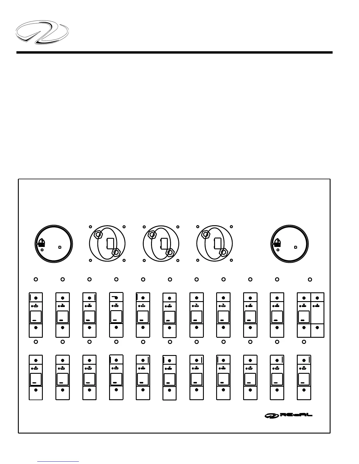
BATTERY MANAGEMENT SYSTEM
The battery management system is an important ingredi-
ent of the yacht’s 12 volt direct current (DC) system. The
battery management panel consists of 3 universal battery
switches, 2 VSR’s and 2 banks of DC breakers plus the
wiring itself. Note the breaker sizes on the diagram below.
Should a replacement become necessary the breaker am-
perage is listed with each breaker.
In some cases the breaker protects a component; in other
cases it may also control a sub-panel or parts of a sub-
panel.
The universal battery switch marked port is part of the
port engine cranking battery circuit. The universal battery
switch marked starboard is part of the starboard engine
battery circuit. Likewise, the switch marked house is part
of the “house” battery circuit. The port VSR is connected
to both the port cranking battery and the house battery.
The starboard VSR is connected to the starboard crank-
ing battery and the house battery.
BATTERY MANAGEMENT SYSTEM
OFF
ELECTRONICS
ON
ON
DASH MAIN
MASTER
20AMP
OFF
LIFT
OFF
ON
5AMP
OFF
CABLE
ON
FWD. SHOWER
PUMP
WINDLASS
150AMP
80AMP
OFF
ON
OIL
20AMP
CHANGER
OFF
80AMP
CABIN MAIN
ON
OFF
ON
ON
ON
20AMP
ON
10AMP
FWD BILGE
PUMP
ACC.
20AMP
OFF
HATCH
ON
90AMP
OFF
MID BILGE
OFF
PUMP
OFF
10AMP
TENDER
OFF
OFF
60AMP
ON
WINCH
PORT
OFF
C
+
D
_
HOUSE
OFF
A
STEREO
MEMORY
CHARGER
ON
ON
ON
30AMP
GANGWAY
ALARM
HIGH WATER
AFT BILGE
10AMP
PUMP
OFF
30AMP
TENDER
ON
OFF
LIFT
OFF
5AMP 10AMP
OFF
ON
OFF
80AMP
ON
OFF
ON
ON
SHOWER
5AMP
PUMP
OFF
CHARGER
80AMP
ON
OFF
PUMP
5AMP
OFF
SHOWER
CHARGER
80AMP
OFF
ON
+
B
_
_
+
STBD
A
OFF
B
VSR
RELAY MODULE
VOLTAGE SENSITIVE
CUT OUT 12.8V DC
CUT IN 13.7V DC
DUAL SENSE
IGNITION PROTECTED
RELAY MODULE
VOLTAGE SENSITIVE
IGNITION PROTECTED
CUT OUT 12.8V DC
CUT IN 13.7V DC
DUAL SENSE
125 AMP
VSR
125 AMP
1
23