95
Programming of relays 2 and 3. Please consult “r1” display.
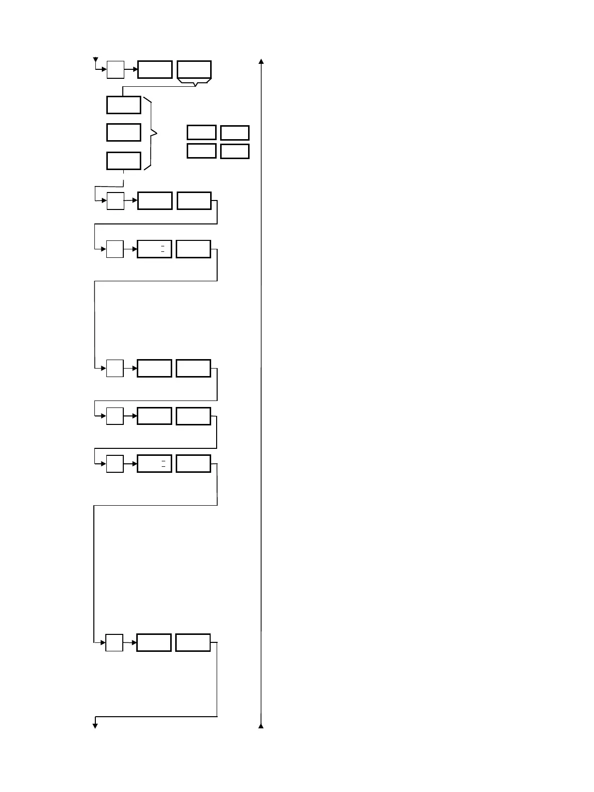
Number of heating stages in the unit.
“0.10” Analog recorder output “1” of the actual value of S1
or S2 in V.
Range 0 to 10 V.
“0.20” Analog recorder output “1” of the actual value of S1
or S2 in mA.
Range 0 to 20 mA.
“4.20” Analog recorder output “1” of the actual value of S1
or S2 in mA.
Range 4 to 20 mA.
Lower measuring range value of the above selected analog
recorder output “1”, e.g. 0 °C/32 °F.
Upper measuring range value of the above selected analog
recorder output “1”, e.g. 300 °C/572 °F.
“0.10” Analog recorder output “2” in V. Range 0 to 10 V.
“0.20” Analog recorder output “2” in mA.
Range 0 to 20 mA.
“4.20” Analog recorder output “2” in mA.
Range 4 to 20 mA.
“FE” Recorder output “2” sends a mV signal correspond-
ing to the actual value display which is equivalent to
that of a J (Fe-CuNi) thermocouple.
“CA” Recorder output “2” sends a mV signal correspond-
ing to the actual value display which is equivalent to
that of a K (NiCr-Ni) thermocouple.
“Cu” Recorder output “2” sends a mV signal correspond-
ing to the actual value display which is equivalent to
that of a T (Cu-CuNi) thermocouple.
Lower measuring range value of recorder output “2”, e.g.
0 °C/32 °F.
P
r2
rEG
ALA
CLC
P
HEA 1
if in
SEt
PEr
→ Section 7.7
r2
ALL
:
etc.
P
o1 0.10
0.10/0.20/
4.20
P
o1
–
0
P
o1
–
300
P
o2 0.10
0.10/0.20/
4.20/FE/
CA/Cu
P
02
–
0
1/2
0 to 500 (°C)
32 to 932 (°F)
0 to 500 (°C)
32 to 932 (°F)
0 to 500 (°C)
32 to 932 (°F)