4.1. Fuse Replacement (AC Input Module)
4.1.1 Unplug the power cord from the AC power Input Module.
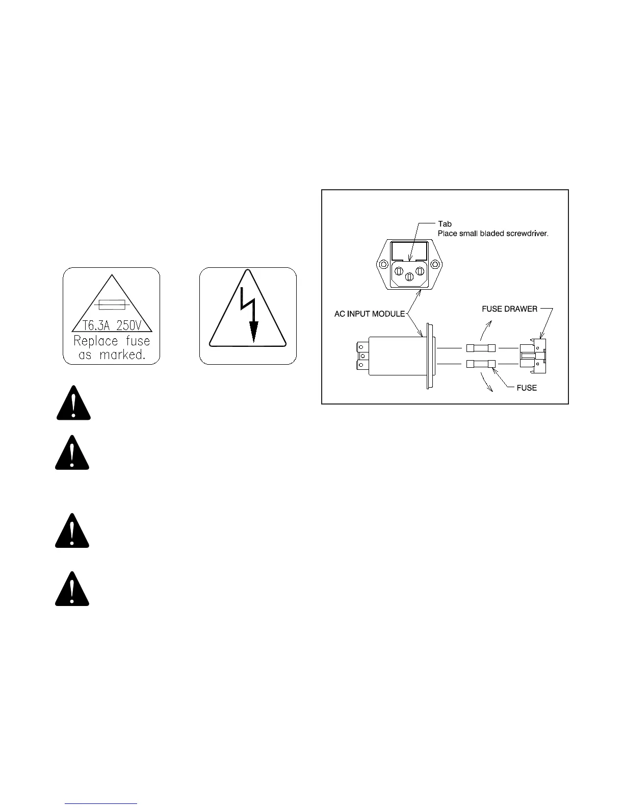
Referring to Figure 4, locate tab. With a tool similar to a small
common screwdriver placed under tab, pry Fuse Drawer out.
Remove the Fuse Drawer by pulling it out with your ngers.
4.1.2 To remove fuses from Fuse Drawer, tilt fuses in direction
of arrows as shown in Figure 4. Examine the fuses, replace
as necessary.
FIGURE 4
AC INPUT MODULE
3.5. Footrest
3.5.1. The Footrest may be retracted by lifting near its
outer edge. When retracted, the Footrest stays in place.
3.6. Headrest
3.6.1. A xed, non-articulating Headrest is the only Headrest
available on the 520 Chair. This Headrest is ergonamically
designed for patients of a wide range of heights.
4.0 LOCATING AND REPLACING FUSES
WARNING: DISCONNECT EQUIPMENT FROM
MAIN INPUT POWER BEFORE PROCEEDING WITH
ELECTRICAL INSPECTIONS OR MAINTENANCE.
AVERTISSEMENT : DÉCONNECTEZ
L’ÉQUIPEMENT DE L’ALIMENTATION
ÉLECTRIQUE PRINCIPALE AVANT DE
PROCÉDER À DES INSPECTIONS ÉLECTRIQUES
OU À DE L’ENTRETIEN.
CAUTION - Replace fuse(s) as marked. All
fuses must be replaced with a fuse of the same
size and rating. Refer to the Wire Diagrams at
the end of this Manual.
PRÉCAUTION : Remplacez le(s) fusible(s)
comme indiqué. Tous les fusibles doivent
être remplacés par un fusible de la même
dimension et de la même valeur. Se référer
aux schémas de câblage à la fin de ce manuel.
The Chair contain two fuses located inside the AC Input Module
in the Base Assembly.
IN-52010