IN-520
7
2. INSTALLATION
2.1. Unpacking
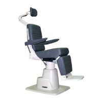
2.1.1. Chair
2.1.1.1. Cut the shipping bands, open the top of the
shipping carton, and remove all packing material and boxes
that can be easily reached. Remove (4) nuts and remove
both base clamping boards.
2.1.1.2. It is recommended that the skid be positioned as
close as possible to the desired Chair location.
2.1.1.3. Remove at least two small shipping blocks stapled
to the top of the skid. The Chair can now be slid and/or
tipped from the skid onto the oor.
2.1.1.4. Do not lift the Chair by the upper structure.
However, the Chair may be tipped or slid into position by
pushing or pulling on the upper structure.
2.1.1.5. With the Chair in positon, remove all remaining
paper pads, plastic, tape, strings, etc.
2.2. Assembly
2.2.1. Headrest
2.2.1.1. Remove the Headrest from its carton. Remove
seat upholstery by pulling the top away from Chair structure.
Attach Headrest to Chair frame using two 5/16 x 5/8
hex head cap screws supplied with Chair.
Replace seat
upholstery. Insert the two locating screws on seat frame
into the two holes in bottom of seat upholstery. Press back
to frame so the hook and loop fabric fasteners engage.
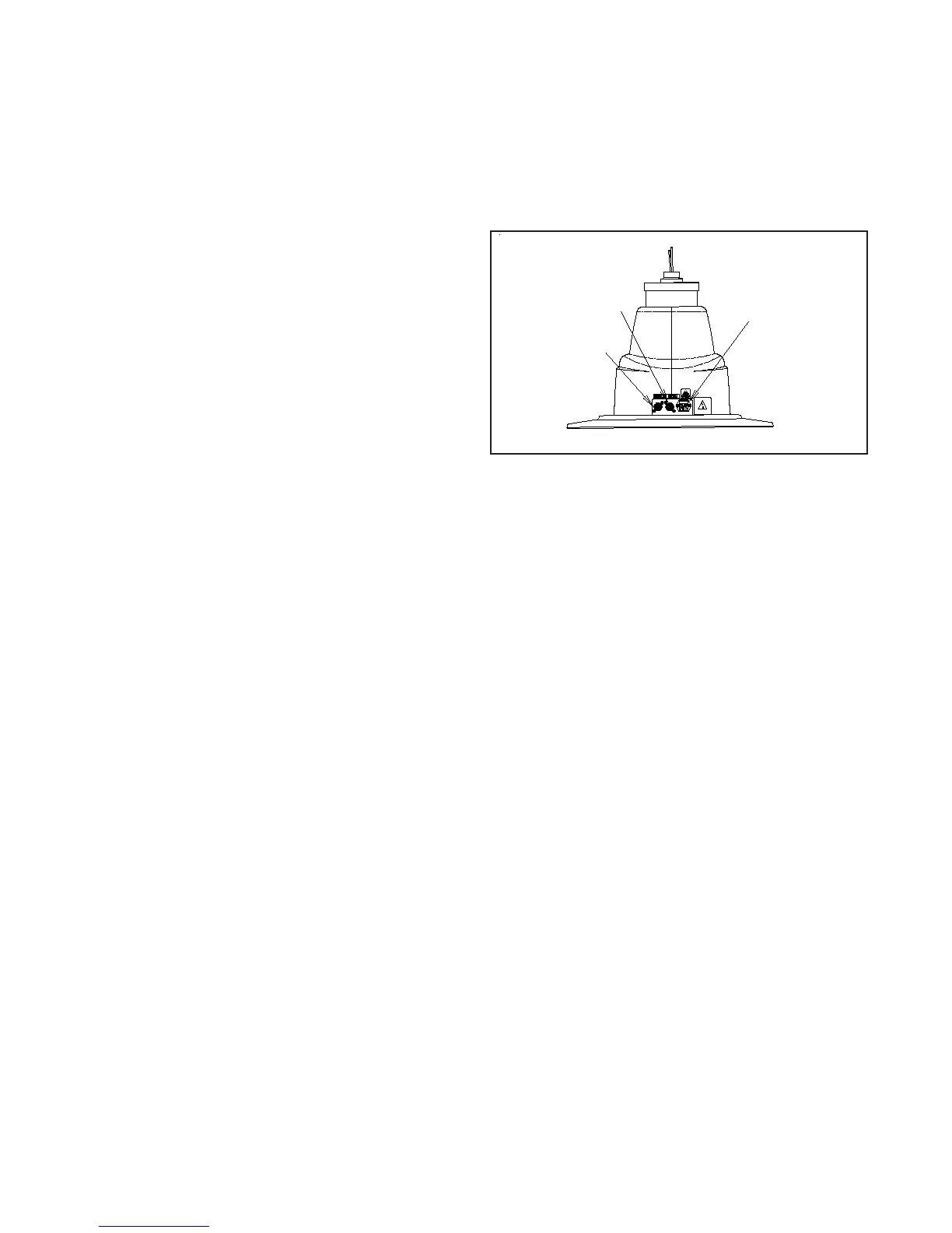
2.2.2. Power Receptacle
2.2.2.1. Locate the Footswitch assembly, Chair Control
Cable, and the Power Cord Assembly. Refer to gure 1 for
receptacle location and attach all cables.
2.2.2.2. To disconnect power to Chair unplug Power Cord
from Instrument Stand or from wall receptacle.
FIGURE 1
BASE
Power Cord &
Fusedrawer
Footswitch
Cable
Chair Control
Cable