9
1
2
3
4
11
12
16
18
21
23
25
26
31
33
30
29
24
6
7
8
10
5
9
15
20
22
28
27
32
35
17
19
34
14
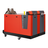
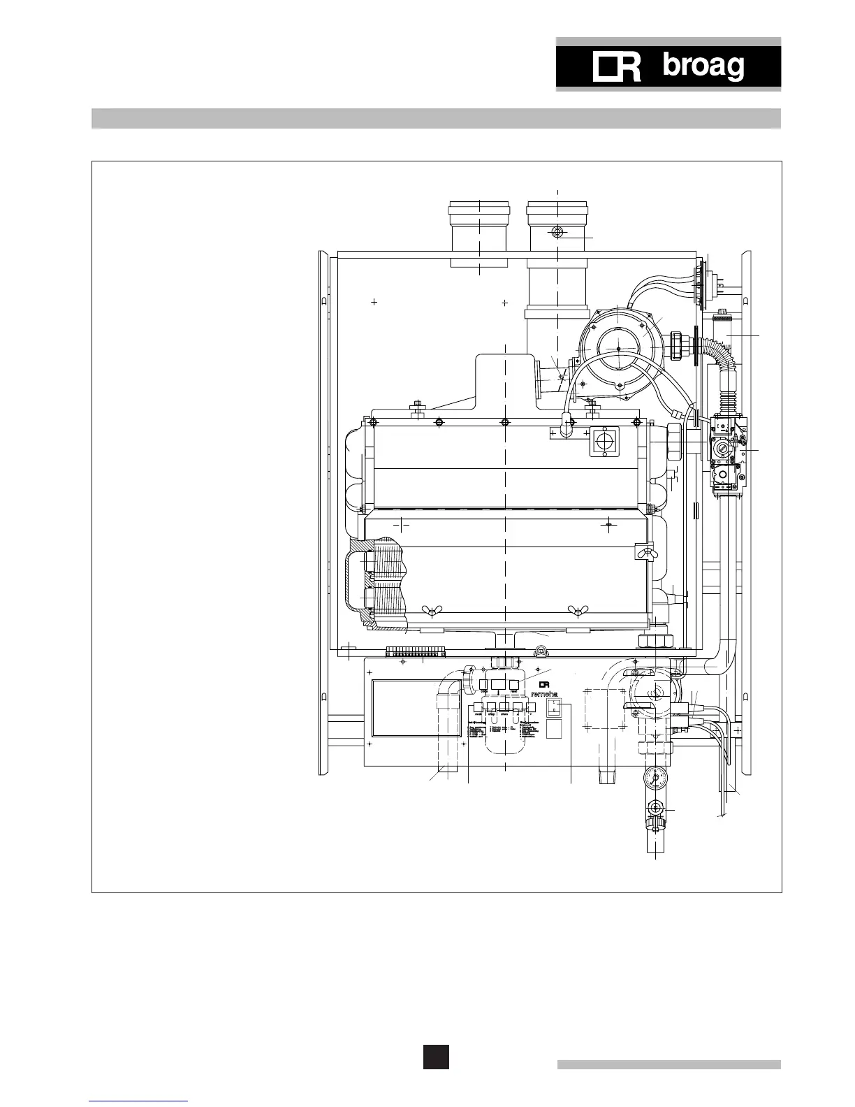
Fig. 06 Boiler layout remeha W40-m ECO
6. BOILER LAYOUT
6.1 Equipment diagram
1. Air supply
2. Flue gas discharge
3. Measure point O
2
/CO
2
4. Air box
5. Slide connector
6. Differential air pressure switch
7. Spring loaded damper
8. Gas injector (behind fan)
9. Fan
10. Automatic vent
11. Burner
12. Ignition/ionisation probe
13. Sight glass
14. Manual air vent
15. Gas combi-block
16. Heat exchanger
17. Flow temperature sensor
18. Inspection cover
19. Return temperature sensor
20. Condense collector
21. Instrument panel
22. Electrical connection strip (X15)
23. Facility for incorporating a
rematic
®
weather compensated
boiler control
24. Condensate discharge
25. Setting keys
26. Read-out display and reset key
27. Burner switch
28. Interface for rematic
®
weather
compensated boiler control
29. Gas connection
30. Pump (only W40-m ECO)
31. Pressure gauge
32. Filling and drain cock
33. Return connection
34. Electrical connection pump and
three-way valve
35. Flow connection
13
 Loading...