5
Operating sequence
Moving the operating switch
to the “I” position puts
the supply air fan into operation
and the program sequence for
the automatic burner is started.
After a few seconds, the electric
solenoid valve opens the gas
supply to the burner. The liquid
gas is transported through a nozzle
under pressure into the mixing
tube. Here, the gas is enriched
with a quantity of oxygen aligned
with the unit output.
The gas/air mixture is ignited
at the burner head by an
electric ignition spark. Ignition
is automatically ended as soon
as a flawless flame burns, and
the automatic burner has taken
over the flame monitoring.
Regulation of the min/max heating
capacity can be implemented
on a stepless basis during unit
operation on the integrated
“power regulation”.
Monitoring the units
It is possible to safely monitor all
functions with the safety devices
of the units.
In the event of irregularities or if
the flame is extinguished, the units
are switched off and interlocked.
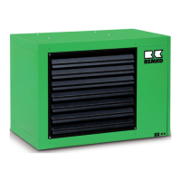
Safety
temperature limiter (STB)
The units are equipped with
a safety temperature limiter
(STB), which interrupts the gas
supply in case of overheating
and electrically interlocks the unit.
s
s
s
Installation instructions
The safety regulations of
the accident prevention
and insurance associations,
the respective regional building
regulations and the combustion
appliances regulations apply
to operation of the unit.
For example, for Germany:
■
Combustion plant order (FeuVo)
for the individual federal states
■
Accident prevention regulations
(UVV) "Heating, flaming and
melting devices for construction
and installation work" (VBG 43)
■
Accident prevention regulations
(UVV) “Use of liquid gas” (BGV
D34)
■
Workplace directives ASR 5
■
Workplace regulations §§ 5 and 14
Outdoor installation
■
The operation of the units
must not present a hazard
or unreasonable loading
■
The unit operator must
ensure that it is not possible
for unauthorised persons
to manipulate either the unit
or the power supply
■
To prevent damage due
to inclement weather, units
installed outdoors must
be adequately protected
Installation in enclosed, well-
ventilated rooms
■
The units are designed without
an exhaust gas connection
according to type, and can
only be used in enclosed rooms
on a conditional basis
■
Reliable extraction
of the combustion gases
must be guaranteed in all
cases in order to exclude
impermissible contamination
of the room air with hazardous
substances
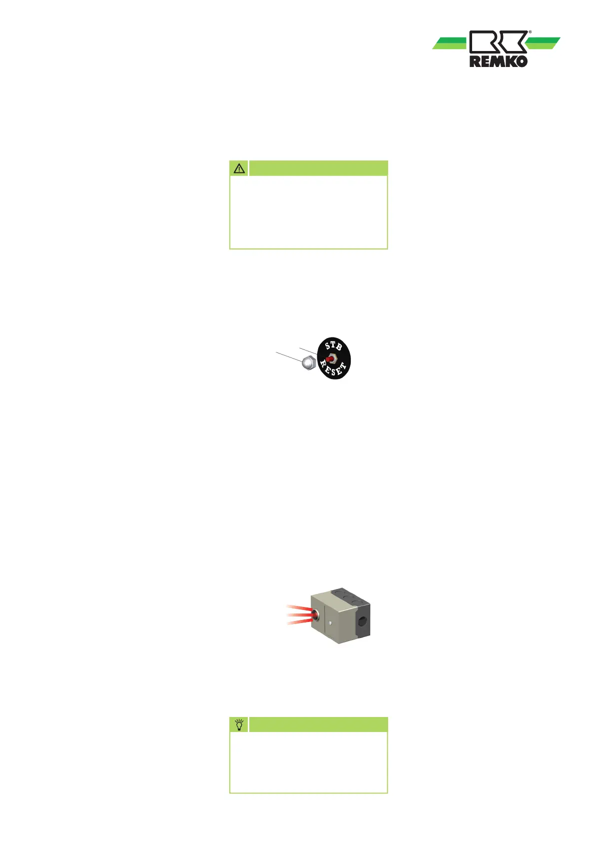
A manual reset of the STB can only
be implemented after the units
have cooled down.
The STB is reset by actuating
the reset key 2.
1. Unscrew the protective cap 1.
2. Push in key 2.
3. Screw the protective cap 1 back
on again.
Automatic burner
In the event of irregularities
or if the flame is extinguished,
the automatic burner switches
off and interlocks the units.
The unit's fault lamp will light up
in this case.
The automatic burner is unlocked
by pressing the malfunction
button.
The automatic burner can be
unlocked after a waiting time
of approx. 60 sec.
1
2
CAUTION
If the safety temperature limiter
has been tripped then the cause
of the malfunction should be
identified and rectified before
resetting it.
NOTE
Before resetting safety
equipment, the cause
of the malfunction must
be identified and rectified.
☞