4 Assembly
4.1 System layout
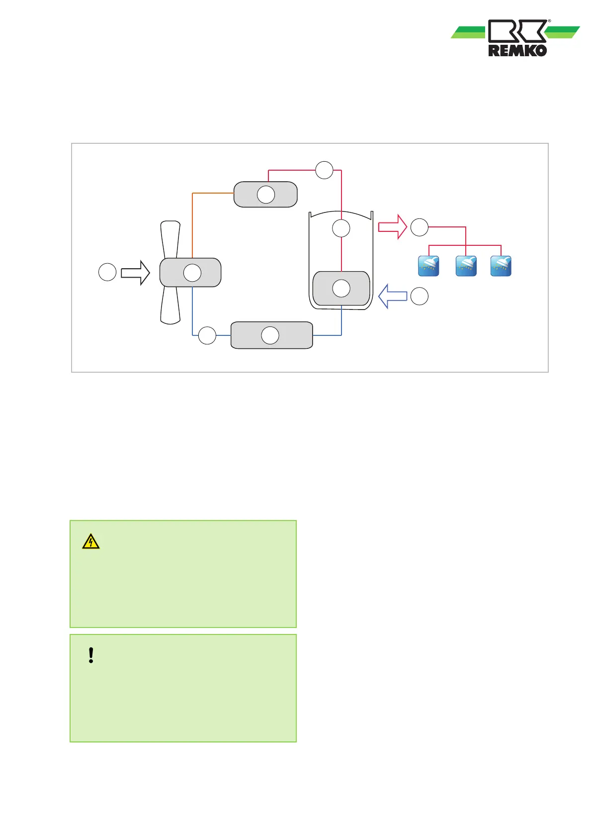
Fig. 6: System layout
1: Cold water inlet
2: Ambient air
3: Storage tank
4: Hot water
A: Compressor
B: Condenser
C: Thermal expansion valve
D: Evaporator
a: Low refrigerant temperature
b: High refrigerant temperature
4.2 General installation notes
DANGER!
Danger of death!
Only authorised specialist personnel are per-
mitted to remove the front panel and the upper
cover plate once the power plug has been
unplugged, because contact with live parts
poses a danger of death!
NOTICE!
Never tilt the unit more than 15 degrees for an
extended period of time. The unit can be tipped
by a max. 60° for short-term transport only
. Pro-
ceed with caution when lifting and lowering the
unit. Horizontal storage or transportation is not
permissible!
n These instructions are to be observed when
installing the heat pump.
n The unit should be delivered as near as pos-
sible to the site of installation in its original
packaging in order to avoid transport damage.
n The unit is to be checked for visible signs of
transport damage. Possible faults are to be
reported immediately to the contractual partner
and the haulage company
.
n Suitable sites for installation are to be selected
with regard to machinery noise and the set-up
process.
n Establish all electrical wiring in accordance
with the relevant DIN and VDE standards.
n The electrical power cables must always be
fastened to the electrical terminals in the
proper manner. Otherwise there is a risk of fire.
n Make sure that pipes carrying water do not
pass through living or sleeping areas.
17
 Loading...