6 Hydraulic connection
Hydraulic connection drawings
All components and safety devices must be provided by the customer.
A
B
a
a
b
c
d
d
e e
f
f
1
1 1
1
1
23
3
3
3
7
1
1
3
7
4
4
55
6
6
88
9
9
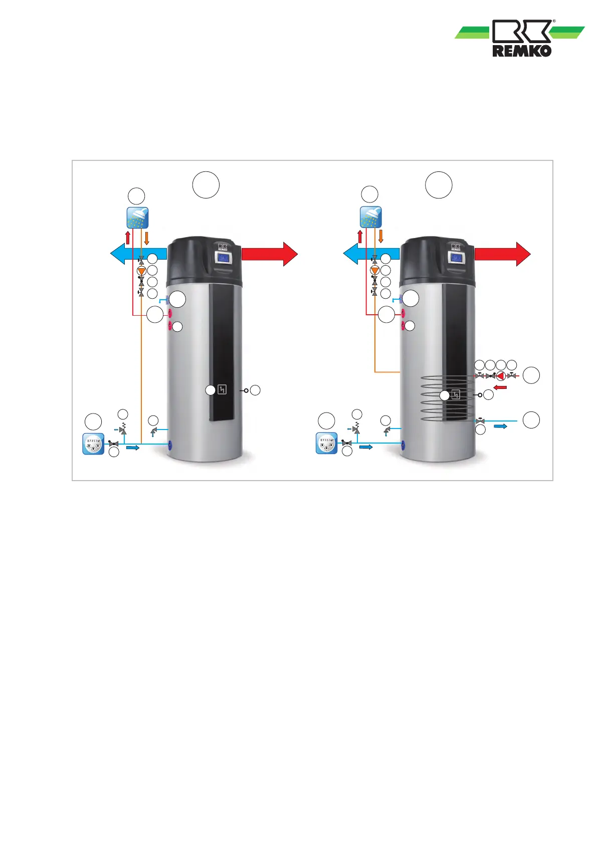
Fig. 11: Hydraulic connection drawings
A: Series RBW 301 PV
B: Series RBW 301 PV-S
a: Cold water inlet
b: Inlet 2nd heat generator
c: Return flow 2nd heat generator
d: Condensate drain
e: Hot water outlet
f: Hot water
1: Shut-off valve
2: Storage tank recharging
(by oil, gas or solar)
3: Flap valve
4: Immersion sleeve (for oil, gas or solar)
5: Storage tank emptying
6: Electric heating coil
7: Circulation pump
8: Safety valve, 6 bar
9: Magnesium anode
Not shown: Safety temperature limiter (STL)
beneath the cover
23

 Loading...