7 Electrical wiring
7.1 General notes
DANGER!
All electrical installation work must be done by
an electrician.
The wiring provided by the customer must comply
with the local regulations. The power supply to the
unit must comply precisely with the voltage and fre-
quency stipulated in the technical data. Get in con-
tact with the local energy supplier if incorrect mains
voltages require correction. Operation of a unit with
incorrect mains voltage constitutes misuse, which
is not covered by the guarantee.
DANGER!
Attention
In order to avoid electric shocks and damage to
the unit, ensure that the electrical installation
has been carried out professionally prior to
establishing the electrical wiring (power plug
with 2 m cable to the socket provided by the
customer).
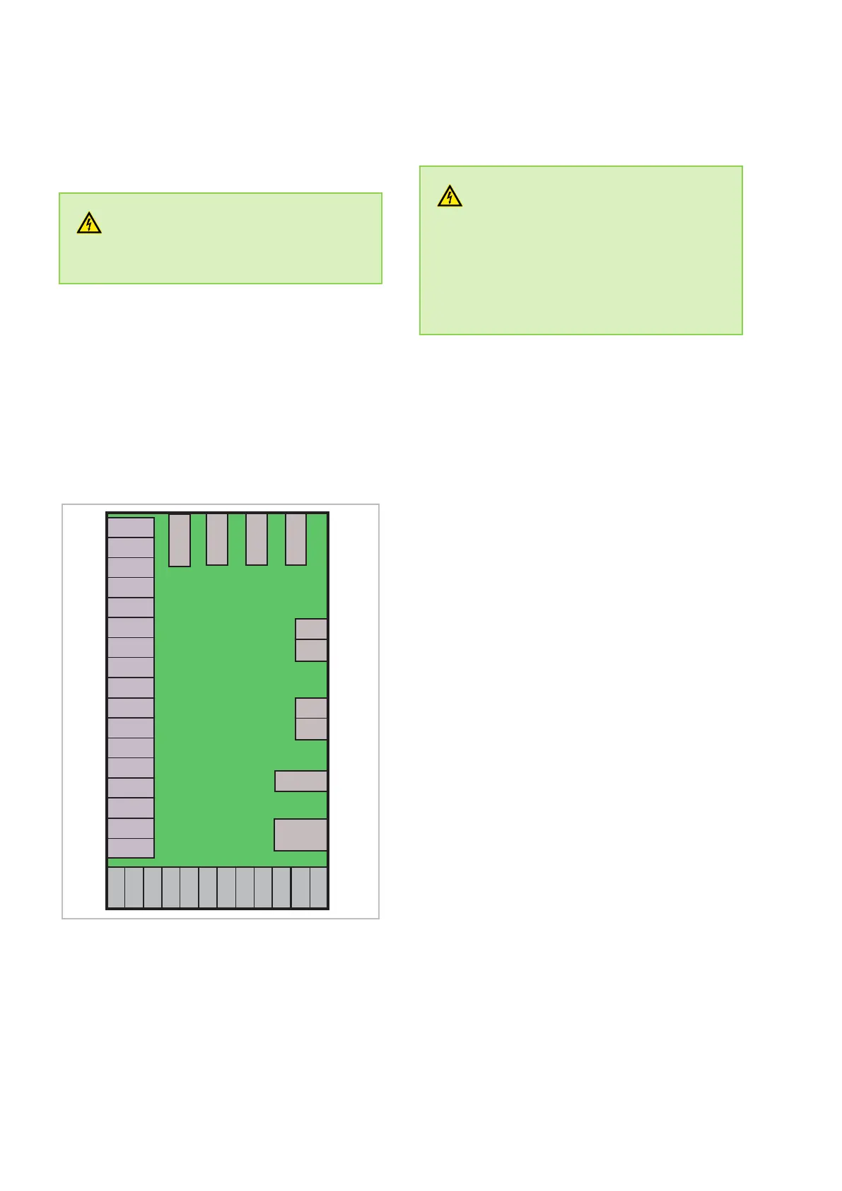
7.2 Connection of the power PCB
3
4
3
4
CN19
CN1
CN2
12V
NET
GND
DI01
GND
DI02
GND
DI03
GND
DI04
GND
DI05
GND
DI06
GND
CN6
OUT3
OUT4
OUT5
AC-N
OUT1 OUT2
GND
AI06
GND
GND
GND
GND
GND
AI05
AI04
AI03
AI02
AI01
HW200
Fig. 14: Connection of the power PCB
AC-N: Neutral conductor
AI01: Air suction temperature
AI02: Temperature storage below
AI03: Temperature storage above
AI04: Temperature evaporator (refrigerant)
AI05: Temperature suction pipe (refrig-
erant)
AI06: Probe collector
CN1: Transformer 1 - 230V
CN2: 12V
CN6: /006
CN19: Not connected
DI01: Jumper
DI02: Jumper
DI03: Jumper
DI04: High pressure
DI05: Not connected
DI06: Contact photovoltaic (potential-free)
12 V/NET/
GND:
Power supply control panel
OUT2(3): Electrical heating coil 230 V
OUT2(4): Power supply
electrical heating coil 230 V
OUT1(3): Compressor
OUT1(4): Compressor power supply 230 V
OUT3: 4-way valve
OUT4: High speed fan
OUT5: Pump solar
REMKO RBW PV series
26
 Loading...